
555 electrical equipment overload and a phase circuit protection device

The circuit operates by utilizing a three-phase AC transformer that steps down the AC voltage to a manageable level. The output of the transformer is connected to a rectifier circuit composed of diodes D1, D2, and D3, which converts the AC voltage to a pulsating DC voltage. This pulsating DC is then smoothed using capacitors to provide a stable DC voltage to the rest of the circuit.
The voltage comparators (IC1, DW1, DW5, R7) continuously monitor the DC voltage levels. They ensure that the voltage remains within preset thresholds, which are crucial for the operation of the subsequent components. If the voltage exceeds or drops below these levels, the comparators will trigger an alert or activate protective measures.
The phase failure protection circuit is vital for maintaining operational integrity in three-phase systems. It employs logic gates and flip-flops to monitor the phase currents. The CD4070 (IC4) acts as a NAND gate, while the 7402 (IC5) serves as a NOR gate, allowing for complex logic operations to determine the presence of all three phases. The CD4013 (IC6) is a dual D-type flip-flop that helps to store the state of the phase detection.
In the event of a phase loss, the output from the phase failure protection circuit is sent to IC3, which is responsible for controlling the relay. When a phase is detected as absent, IC3 activates the relay, effectively disconnecting the power supply to prevent damage to the equipment. This relay control circuit is crucial for protecting sensitive electrical equipment from potential overloads or phase imbalances, ensuring safe and reliable operation in industrial environments.
Overall, this circuit design provides a robust solution for electrical equipment protection, combining voltage monitoring, phase detection, and automatic disconnection mechanisms to enhance system reliability and safety. As shown for the electrical equipment overload and phase failure protection circuitry. The device consists of + 12V, + 5V DC power supply, AC transformer, voltage comparators, timers blockade, relay control circuit and phase loss protection circuit. Wherein the DC power supply for the entire circuit DC voltage.The three-phase AC transformer LH current flowing through the coupling proportionally out and were treated D1C1, D2C2, D3C3 rectified filtered Bo Houjia to the voltage comparator (IC1, DW1, DW5, R7) and phase failure protection circuit (IC4, IC5, IC6). By the lack of IC4 (CD4070), IC5 (7402), IC6 (CD4013) and other components of phase protection circuit for detecting and determining the presence or absence of three-phase current, if one phase, set the IC3, relay pull-J together, the power supply is disconnected for phase protection.
Related Circuits
Charging a mobile phone or cellphone battery presents a significant challenge while traveling, as a power supply source is often not readily available. If the cellphone remains switched on continuously, its battery can deplete within five to six hours,...
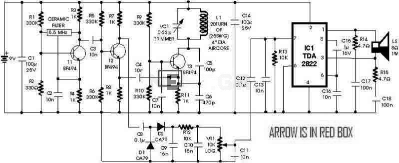
This is a simple metal detector utilizing a TDA2822 and several NPN transistors. An arrow indicates the signal flow direction from the Emitter of transistor T3 to the 10nF capacitor C4, which is opposite to the typical left-to-right flow...
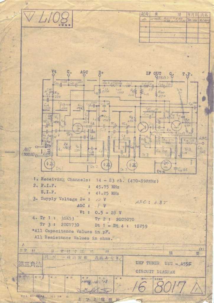
This section will list several projects that enable the construction of RF design test equipment. Some projects will require microwave construction techniques and basic electronic skills, but the tools created will be comparable to those used by professionals. The...
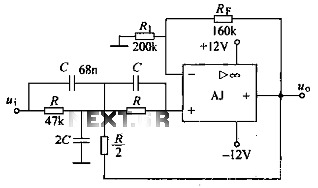
A band-stop filter (BSF) utilizing an integrated operational amplifier is designed to suppress signals within a specific frequency band, allowing signals outside this band to pass with minimal attenuation. This configuration is achieved through a two-stage network, which employs...
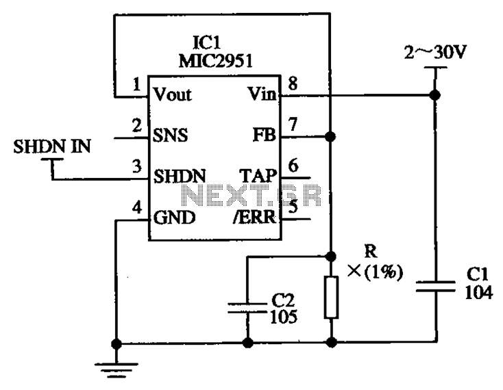
The circuit illustrated in the figure utilizes the low-drift current source circuit MIC2951, which is designed to provide specific output current values. The MIC2951 is a precision voltage regulator that can also be configured to function as a low-drift current...
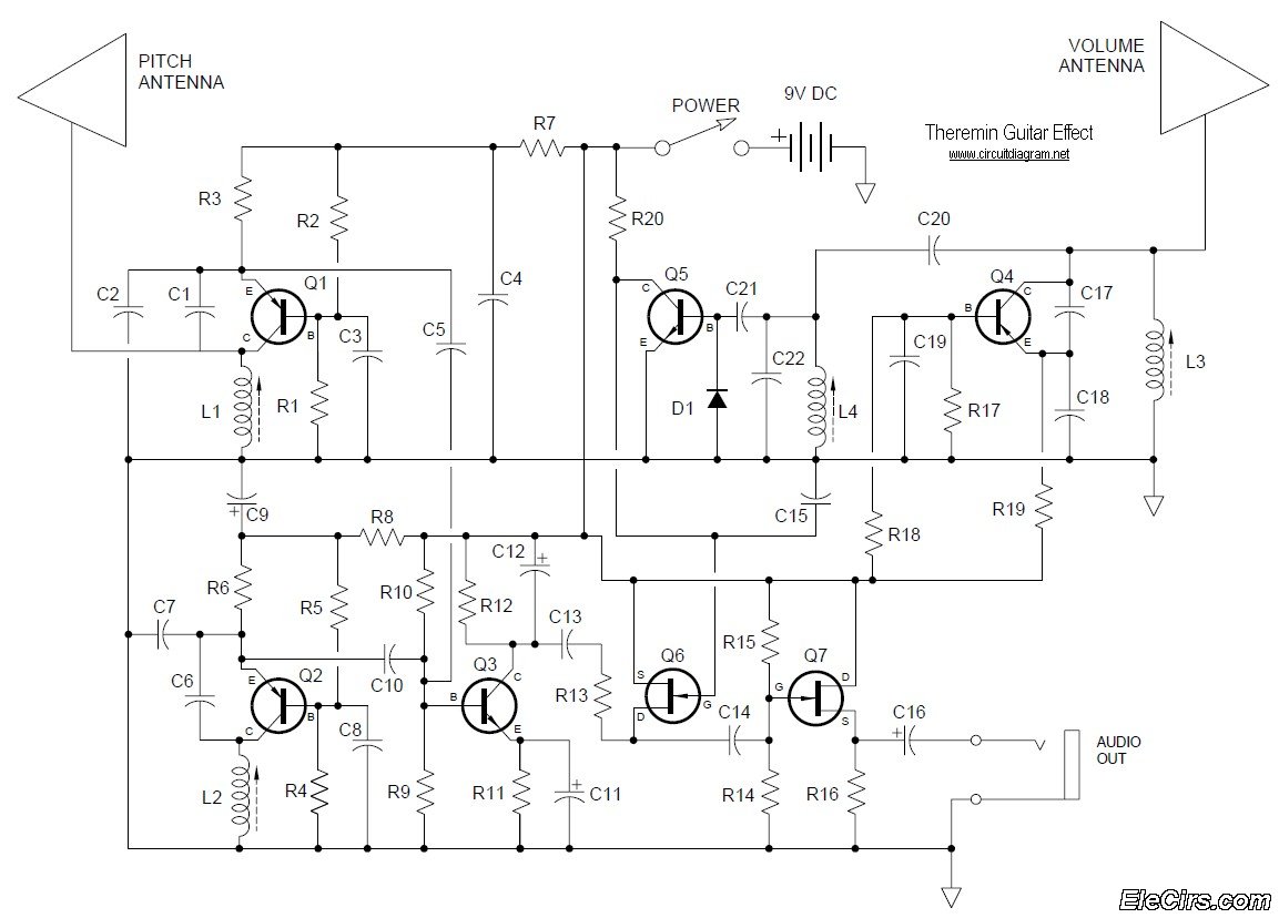
Below is the circuit diagram for the Theremin music instrument effect. A guitar or instrument amplifier is an ideal companion for the Theremin, allowing for bass or treble boost as desired, as well as fuzz (distortion) or reverberation if...