
555 flow-control circuit diagram of a lantern

The electronic schematic described features a dual 555 timer configuration, where the first timer operates in monostable mode to generate a pulse that controls the operation of the SCRs. The circuit begins with a power supply that provides the necessary voltage (Vdd) to the timers and SCRs. Upon activation, the 555 timer (IC1) generates a high signal at its output (pin 3), which triggers SCR1. The SCRs are semiconductor devices that allow current to flow only when they are triggered by a gate signal, making them ideal for controlling high-power loads such as lights.
The capacitor C3, charged through resistor R3, plays a critical role in timing the operation of the first timer. The charging of C3 is monitored, and once it reaches the threshold of 2/3 Vdd, the second 555 timer (IC2) is set. This timer, configured similarly, produces a high output that activates SCR2, allowing for sequential control of additional lights. The use of capacitors (C3 and C5) in conjunction with resistors (R3) ensures that the timing of the light activation is precise and can be adjusted based on the resistor values.
The entire circuit is designed to handle a current of up to 150mA, which is suitable for driving multiple incandescent or LED lights, depending on the specifications of the SCRs used. The choice of SCRs affects the overall power consumption and efficiency of the circuit. This design is particularly useful for applications requiring cyclic lighting effects, such as decorative lighting, stage lighting, or other visual displays. Proper heat sinking and current limiting measures should be considered to ensure the reliability and longevity of the SCRs under continuous operation. As shown, the three lights control circuit 555 as the core, consisting of cyclic trigger monostable delay circuit, the brightest of the SCR control the cycle turned, lights wer e lit, the shape of the water. When 3 feet of IC1 goes high, SCR1 is turned on, it controls the lights, at the same time, 3 feet high potential for C3 is charged by R3, C3 when charging voltage is higher than 6 feet threshold level 2/3Vdd when, IC2 is set, the output high, SCR2 turns on, it controls the lights, while the charge for C5 ., and so on, turned on lights. How much power is different depending on the thyristor SCR lamp 555 using bipolar drive current up to 150mA.
Related Circuits

This circuit is designed to measure the inductance of an inductor labeled LX. The output of the circuit generates a TTL square wave, with its frequency being directly related to the inductance being measured. The output from the inductance...
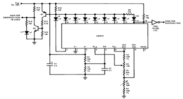
By utilizing several resistors, LEDs, and the LM3914 bar/dot display driver IC, it is possible to create a straightforward 5V voltmeter monitor circuit. This circuit offers TTL-compatible undervoltage and overvoltage warning signals. A complete circuit schematic is available below. The...
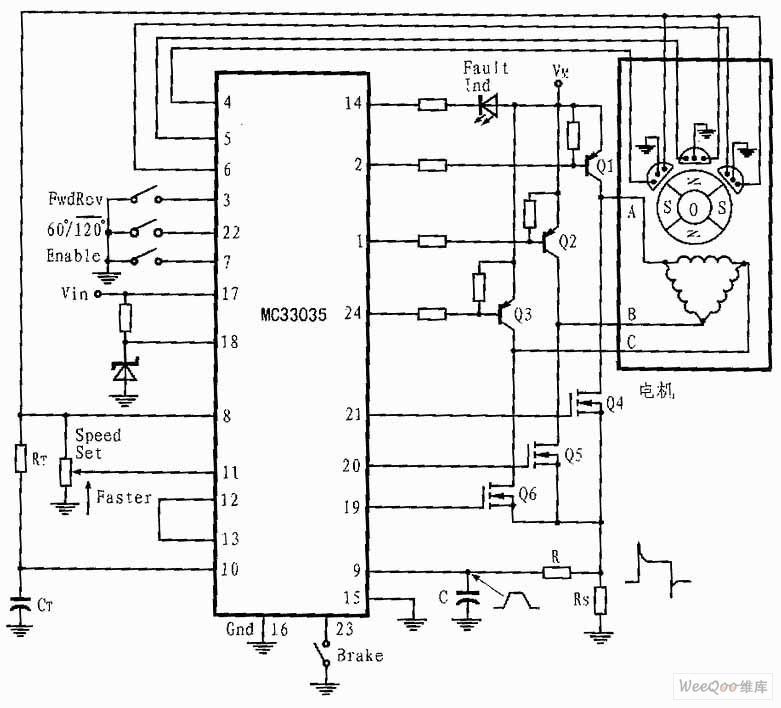
The presented three-phase application circuit features a motor controller circuit connection diagram that operates using a full-wave six-step method. The power switch is a Darlington PNP type, while the lower power switch is an N-channel power MOSFET. Each device...
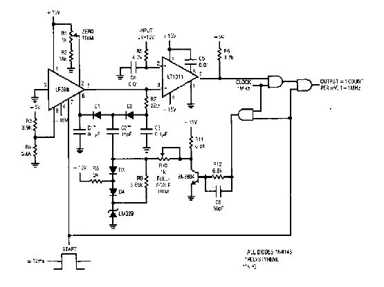
The simple 4-digit converter circuit has an output count of 1, designed to operate within a frequency range of f-IMHz to 10.000. All diodes used in the circuit are IN4146, and the capacitors are made of `POLYSTYRENE` NPO. The...
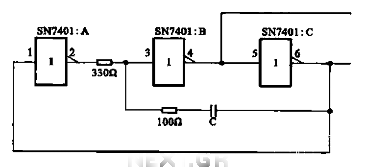
The clock signal generating circuit utilizes an RC configuration, commonly applicable in most TTL systems. This circuit requires a set of six inverters, specifically three inverters from the SN7401 series. The clock frequency is determined by the values of...
This is a line follower designed to trace grid-type tracks. It features five line sensors for tracking the line. This arrangement of five sensors has proven effective, having been used multiple times with successful results. The device is named...