
Analogue to digital converter circuit

The described 4-digit converter circuit is a frequency-to-voltage converter designed for applications requiring precise frequency measurement and digital display. The LF398, a high-speed sample-and-hold amplifier, serves as the primary input component, allowing for accurate signal processing of the incoming frequency signal, which can range from sub-MHz to 10 MHz.
The circuit architecture typically includes a diode-based rectification stage, where the IN4146 diodes are employed to ensure fast switching and minimal forward voltage drop, enhancing the overall accuracy of the frequency conversion. The use of polystyrene capacitors, known for their low dielectric losses and stability, aids in maintaining the performance of the circuit across varying temperatures and frequencies.
The output stage of the circuit is configured to drive a 4-digit display, which may be a 7-segment LED or LCD, depending on the design requirements. The digital representation of the input frequency is achieved through a combination of counting and converting the analog signals processed by the LF398, providing a direct and readable output.
Overall, this circuit is suitable for applications in digital frequency meters, signal processing equipment, and various measurement tools where precise frequency conversion is essential. Proper attention to component selection, layout, and power supply considerations will ensure optimal performance and reliability in practical implementations.That simple 4 digits converter circuit has OUTPUT COUNT = 1 according to my f-IMHz to 10.000. All diodes are IN4146 `POLYSTYRENE` NPO. The circuit uses the LF398 at input 🔗 External reference
Related Circuits
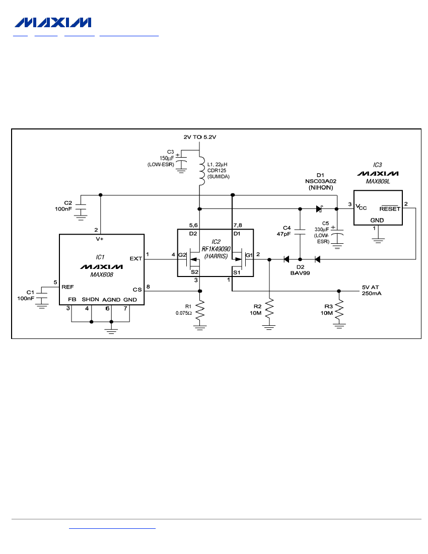
To ensure a full-load start-up, the additional circuitry in this regulated boost converter disconnects the load until the output voltage reaches regulation. Proper operation necessitates a gate-drive voltage adequate to maintain low on-resistance in the switching MOSFET; however, during...
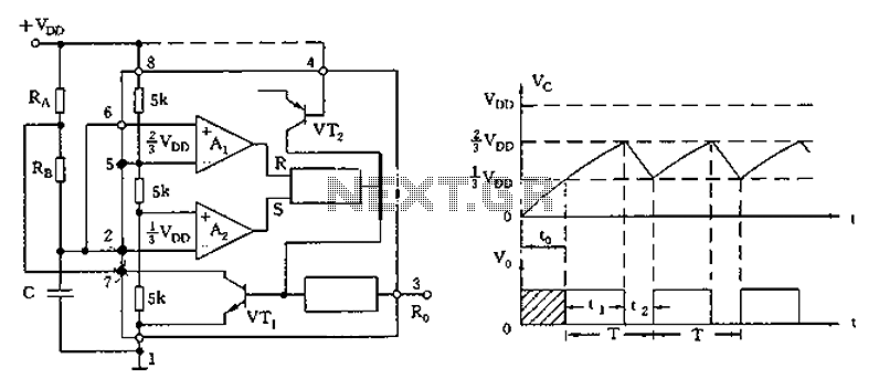
The circuit diagram illustrates the 555 timer (or 556 timer in half configuration) configured in astable multivibrator mode. It features three resistive and capacitive elements connected as shown. In one-shot mode, the trigger terminal (pin 2) is connected to...

The circuit serves as a signal source for calibration level meters or sensor-driven differential transformers. The oscillation frequency is determined by the 74HC04, producing a frequency of 1 kHz through resistor R. The supply voltage of the circuit changes...
An efficient 4-stage stabilized power supply unit is designed for testing electronic circuits. This unit provides well-regulated and stabilized output, which is essential for most electronic circuits to yield accurate results. The circuit features audio-visual indicators to signal a...
The demand for high-quality electric energy in modern industrial development is increasing, making it essential to provide safe and reliable green power to energy consumers. Uninterruptible Power Supplies (UPS) are crucial for improving electric energy quality and ensuring the...
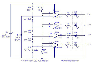
This circuit is a practical device that, when installed in a vehicle, displays the voltage of the car battery using an LED dot display. The meter circuit utilizes four comparators formed from a quad op-amp, specifically the LM324. The...