
555 IC for Square Wave Tone Burst Generator

The circuit described involves a square wave generator that produces tone bursts upon activation of a pushbutton switch. When the pushbutton is pressed, it allows current to flow, resulting in a voltage increase at Pin 4. This voltage must exceed a defined threshold level to initiate the generation of a square wave signal. The duration of the square wave output is directly proportional to the time that the voltage at Pin 4 remains above this threshold.
To implement this functionality, a timer IC, such as the 555 timer, can be configured in monostable mode. In this configuration, the output will transition from low to high when triggered by the pushbutton. The duration of the high output state can be set by selecting appropriate resistor and capacitor values connected to the timing circuit. The resistor (R) and capacitor (C) values determine the time constant (τ = R × C), which in turn defines how long the output remains high.
Additionally, components such as a transistor may be used to amplify the square wave signal to drive a speaker or buzzer, producing an audible tone. The circuit may also include a diode for protection against reverse polarity and a capacitor for smoothing the power supply. Proper decoupling capacitors should be placed near the IC to ensure stable operation, minimizing noise and voltage fluctuations.
Overall, this circuit design allows for the generation of adjustable tone bursts, making it suitable for applications in alarms, timers, and sound effects in various electronic devices.Square wave tone bursts is provided by depressing the pushbutton. It`s duration depends on the duration for which the voltage at Pin 4 exceeds a threshold.. 🔗 External reference
Related Circuits
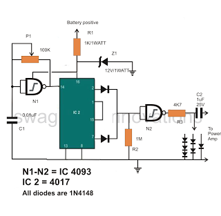
All the stages involved are designed to enable a frequency response of 20 to 100 kHz. Although such a high degree of frequency response is not necessary for this application, none of the stages have been eliminated as they...
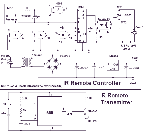
This circuit will allow you to turn on any piece of equipment that operates on 115 volts AC. The receiver circuit is based on the Radio Shack infrared receiver module (MOD), part number 276-137. It is also available from...
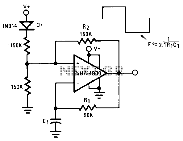
This self-starting fixed-frequency oscillator circuit provides excellent frequency stability. R1 and C1 form the frequency-determining network, while R2 delivers the regenerative feedback. Diode D1 improves stability by compensating for the difference between VaH and VsurrLY. In applications where a...
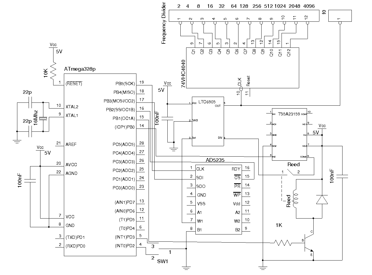
Most commercial-grade signal generators provide more than just sinusoidal waveform output, but they tend to be expensive for casual use. This article presents a simple wideband signal generator built around Linear Technology's LTC6905 Silicon Oscillator, capable of generating frequencies...
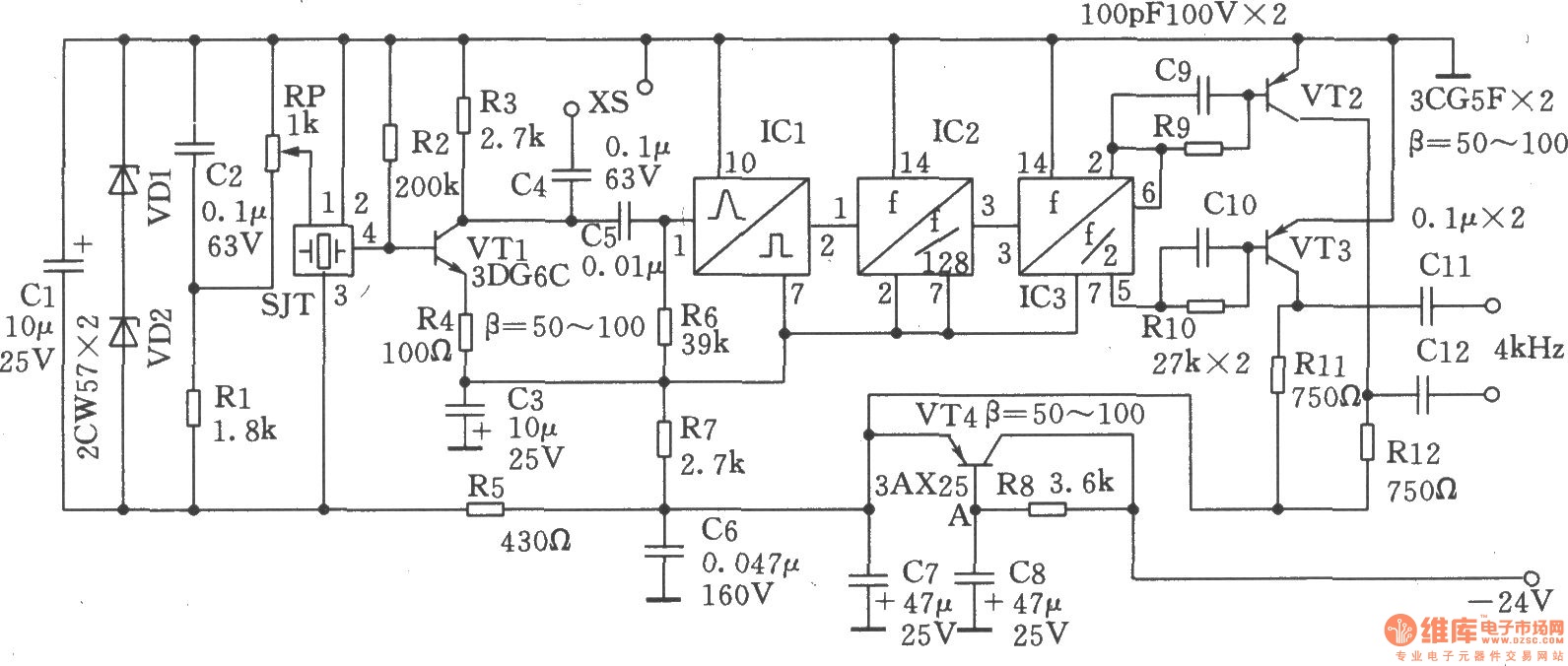
The circuit SJT is a 1024 kHz warming crystal oscillator. The circuit is illustrated in the accompanying chart. Due to the low output signal level, a transistor (VT1) is employed as a buffer amplifier. The base bias resistor (R2)...
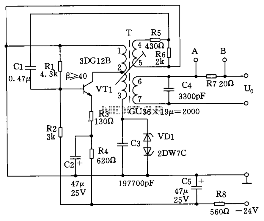
The circuit depicted in the figure allows for the selection of optimal operating conditions and a suitable allocation of the temperature coefficient for the resonant circuit components. The resonance occurs at both ends of the circuit. Additionally, the exchange...