
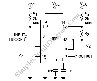
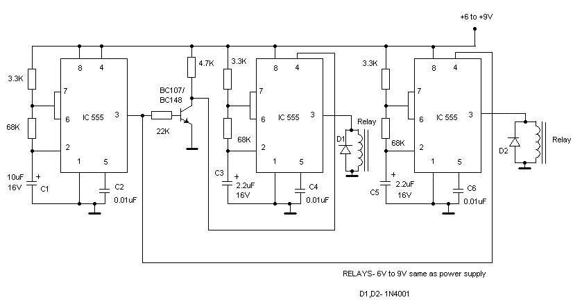
555 IC Oscillator with 50% Duty Cycle

The 555 timer IC is a versatile and widely used component in electronic circuits, particularly for generating square wave signals. When configured in astable mode, the 555 timer can produce a continuous square wave output, where the frequency and duty cycle can be adjusted by selecting appropriate resistor and capacitor values.
For symmetric oscillation with a 50% duty cycle, the circuit typically includes two equal resistors (R1 and R2) connected to the discharge and threshold pins of the 555 timer, along with a timing capacitor (C1) connected to the ground. The output frequency (f) can be calculated using the formula:
f = 1.44 / ((R1 + 2R2) * C1)
In this configuration, the charge and discharge times are equal, resulting in a 50% duty cycle.
In addition to the basic 555 oscillator setup, the use of diodes can enhance circuit functionality. Diodes can be incorporated to create distinct charging and discharging paths for the timing capacitor. This allows for greater control over the timing characteristics of the oscillator, enabling variations in duty cycle while maintaining the overall oscillation frequency.
For instance, one diode can be placed in series with the resistor connected to the discharge pin, while another diode can be connected to the resistor linked to the threshold pin. This arrangement allows the capacitor to charge through one path and discharge through another, effectively modifying the duty cycle without altering the frequency significantly.
In summary, a square wave oscillator using the 555 IC can achieve symmetric oscillation with a 50% duty cycle through careful selection of resistor and capacitor values, while the incorporation of diodes provides additional flexibility in managing the charging and discharging processes.A square wave oscillator using 555 IC can be configured to give symmetric oscillation (50% duty cycle). Other circuit uses diodes to split the charging and the. 🔗 External reference
Related Circuits

The circuit illustrated in Figure 4 is an AC timing circuit designed to operate for 4 hours. It utilizes the BH4024, a 7-stage serial binary counter/divider, in conjunction with a 555 timer circuit. The circuit is activated by a...
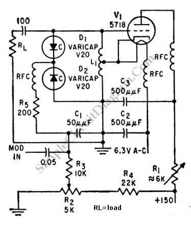
This is a 100 MHz varicap oscillator circuit. It can provide modulation signals of less than 28 V and a frequency deviation of 28 MHz peak-to-peak. The 100 MHz varicap oscillator circuit utilizes a varactor diode, which is a semiconductor...
A high-quality tone burst generator can be constructed using a 556 Dual Timer. The first half of the timer can be configured as a one-shot, while the second half can function as an oscillator. The 556 Dual Timer is an...
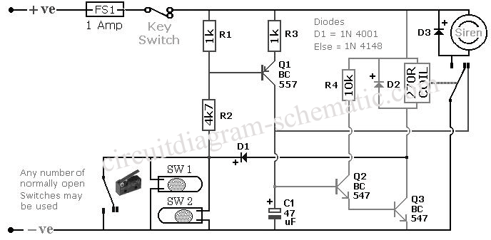
This circuit is designed to create an early warning alarm system for any form of theft that is important to the owners of a motorcycle or bicycle. This alarm system can utilize a number of normally open switches, such...
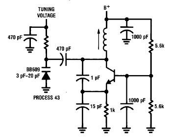
A simple high-efficiency Colpitts oscillator is utilized in higher frequency ranges, specifically above 50 MHz. Colpitts oscillators are preferred as stray circuit capacitance is in parallel with the desired feedback capacitance, preventing undesirable spurious resonances that may occur with...
This circuit uses three easily available 555 timer ICs. All three work as astable multivibrators. The first 555 has an on period and off period equal to 1 sec. This IC controls the on/ off periods of the other...