
Advanced LED Flasher with 555

This circuit employs three 555 timer integrated circuits (ICs) configured as astable multivibrators. The first 555 timer (IC1) generates a square wave signal with an equal on and off duration of 1 second. This output controls the operation of the subsequent two 555 timers (IC2 and IC3), which are responsible for flashing two separate bulbs connected via relay contacts.
The flashing rate of the bulbs is set to 4 flashes per second, which corresponds to a period of 250 milliseconds for each flash. The circuit incorporates diodes for protection, safeguarding the 555 timer ICs from voltage spikes that could occur during operation. It is crucial that the relays used in the circuit have an impedance greater than 50 ohms, ensuring that the current drawn does not exceed 200 mA, which is important for maintaining the integrity and longevity of the components.
The sequence of operation is as follows: the bulb connected to the first relay will flash for approximately 1 second, followed by the bulb connected to the second relay flashing for the same duration. This cycle continues to repeat, allowing for an alternating flashing effect.
Adjustments to the flashing rates can be made by varying the capacitance values of capacitors C3 and C5. To achieve the desired flashing frequency, these capacitors should be of equal value and should be less than the value of capacitor C1, which primarily dictates the change-over rate of the flashing cycle. A higher capacitance for C1 results in a longer change-over time.
The configuration of the relay contacts can significantly affect the operation of the bulbs. When using normally open relay contacts, one bulb will remain off while the other is flashing. Conversely, if normally closed relay contacts are employed, one bulb will be continuously on while the other flashes. This flexibility in the relay configuration allows for customization of the circuit's behavior based on specific application needs.This circuit uses three easily available 555 timer ICs. All three work as astable multivibrators. The first 555 has an on period and off period equal to 1 sec. This IC controls the on/ off periods of the other 2 555s which are used to flash two bulbs through the relay contacts. The flashing occurs at a rate of 4 flashes per second. The diodes are used to protect the 555 ICs from peaks. The relays should have an impedance greater than 50ohms i.e, they should not draw a current more than 200mA.
The flashing sequence is as follows: The bulb(s) connected to the first relay flashes for about 1 sec at a rate of 4 flashes per second. Then the bulb(s) connected to the second relay flashes for 1 sec at a rate of 4 flashes per second. Then the cycle repeats. The flashing rates can be varied by changing the capacitors C3 and C5. A higher value gives a lower flashing rate. Note that the values of C3 and C5 should be equal and should be less than that of C1. The value of C1 controls the change-over rate ( default 1sec). A higher value gives a lower change-over rate. If you use the normally open contacts of the relay, on bulb will be OFF while other is flashing,and vice versa.
If normally closed contacts are used, one bulb will be ON while the other is flashing. 🔗 External reference
Related Circuits
This schematic illustrates a simple yet effective LED dimmer circuit utilizing the well-known voltage regulator IC LM317T. The LM317T can function as a current regulator, as demonstrated in this circuit. It features ten super bright white LEDs, although the...
Flyback LED drivers are versatile as they can be utilized in applications with input voltages either above or below the necessary output voltages. They feature a straightforward circuit configuration that maintains a constant LED current without the need for...
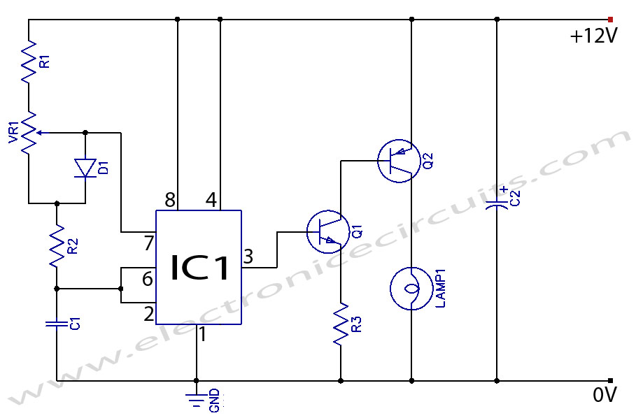
When the potentiometer is in the upper position, the capacitor charges rapidly through both 1k resistors and the diode, resulting in a brief positive interval and an extended negative interval, which dims the lamp to near darkness. Conversely, when...
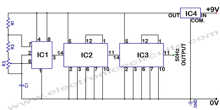
Accurate 50Hz Oscillator Circuit Using 555 and 7490. This circuit generates a 50Hz pulse. It consists of a 555 timer and two 7490 divide-by-ten counters. The circuit utilizes a 555 timer configured in astable mode to produce a square wave...
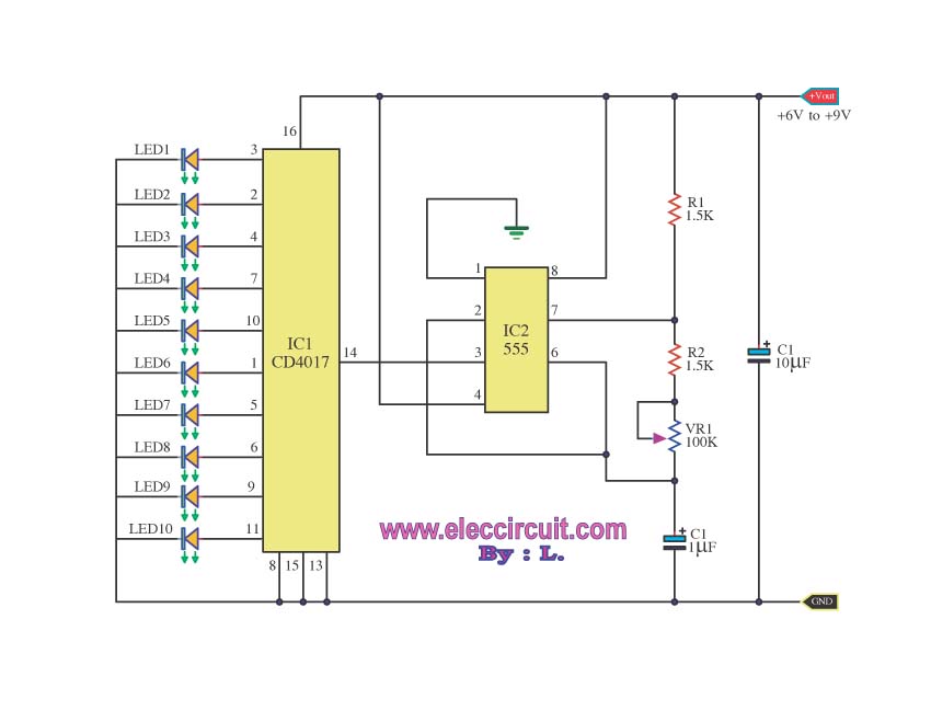
For constructing a 10 LED Chaser circuit, it is recommended to start with this design. It utilizes the widely used and cost-effective IC-4017 decade counter. The 10 LED Chaser circuit is an engaging project that demonstrates the sequential lighting of...
IC4, C1, R1 and R2 are used for the clock pulse which is fed to both the counters IC2 and IC3 Pin 14. IC1 is a Flip Flop and is used as a switch to enable either IC2 or...