555 IC For IR Remote Control Extender Circuit

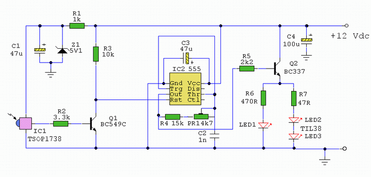
The following circuit illustrates the use of a 555 integrated circuit (IC) for an infrared (IR) remote control extender circuit. Features include support for 850 nm and 950 nm signal wavelengths, along with the capability to generate control pulses.
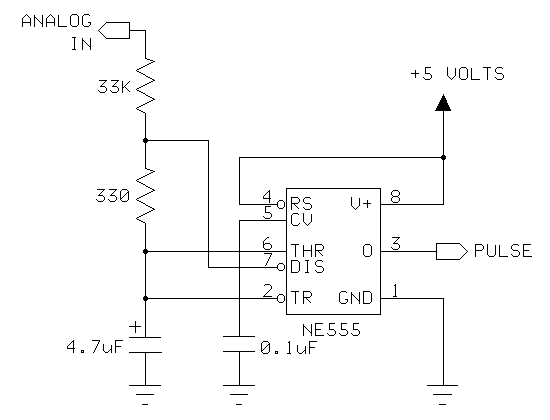
The circuit utilizes the 555 IC, which is a versatile timer and oscillator, to extend the range of IR remote controls. The design typically involves configuring the 555 timer in monostable or astable mode, depending on the specific requirements of the application. In this context, the monostable mode is often preferred for generating a single pulse in response to an incoming IR signal.
The essential components of the circuit include the 555 timer, resistors, capacitors, and an infrared LED. The 555 timer is powered by a suitable DC voltage source, typically in the range of 5V to 15V. A photodiode or phototransistor is employed to detect the incoming IR signals. When the IR signal is received, it triggers the 555 timer, which then sends out a control pulse through the output pin.
The output from the 555 timer can be connected to an IR LED, which emits the IR signal at the specified wavelengths of 850 nm or 950 nm. This allows for the extension of the remote control signal, enabling devices to be controlled from a greater distance or through obstacles that would otherwise block the direct line of sight.
For optimal performance, the values of the resistors and capacitors in the circuit must be calculated to set the desired timing intervals for the control pulses. Additionally, the circuit may include a low-pass filter to reduce noise and improve the reliability of the signal detection. Overall, this IR remote control extender circuit effectively enhances the functionality of standard remote controls by utilizing the capabilities of the 555 timer IC.The following circuit shows about 555 IC For IR Remote Control Extender Circuit. Features: 850 and 950 nm signal, the control pulses and a .. 🔗 External reference


