
555 LED Pulsing Breathing Circuit

The breathing LED circuit utilizes the 555 timer in astable mode, where it generates a continuous square wave output. This output can be used to control the brightness of the LED by modulating the current through it. The frequency and duty cycle of the square wave can be adjusted by changing the values of resistors and capacitors connected to the timer. Typically, two resistors (R1 and R2) and one capacitor (C1) are used to determine the timing characteristics.
In this circuit, the 555 timer operates with a supply voltage of 5 volts, which is suitable for driving LEDs that require around 3.8 volts. The choice of a lower voltage supply helps to minimize power loss in the transistor used to switch the LED on and off. The transistor, which acts as a switch, is connected to the output pin of the 555 timer, allowing it to handle higher currents required by the LED without overheating or exceeding its ratings.
To ensure the circuit functions correctly at 5 volts, careful selection of resistor and capacitor values is essential. The timing components should be calculated to achieve the desired breathing effect, which typically involves a gradual increase and decrease in brightness. This can create a visually appealing pulsing effect that simulates breathing.
For users attempting to adapt the circuit for a 12-volt supply, it is crucial to recalculate the resistor and capacitor values accordingly, as well as to select a suitable transistor that can handle the increased voltage and current requirements. Additionally, a voltage regulator may be necessary to step down the 12 volts to an appropriate level for the LED operation.
Overall, this breathing LED circuit is an effective and visually engaging project that showcases the versatility of the 555 timer chip in various applications, particularly in decorative lighting for PC modifications.Here is a circuit for simulating breathing / pulsing LED with the 555 timer chip. It became very popular and i received many comments and emails with people that made this circuit and worked fine, as well as comments with people that had troubles converting it to operate at 12 volts supply. It was designed to operate with 5 volts, because i plan to use it for a future PC mod. Since the PC power supply has 5 volts output, and since the LEDs that i plan to use require 3.8 volts to operate, choosing 5 volts for supply was the best choice to minimize power dissipation on the transistor
🔗 External reference
Related Circuits
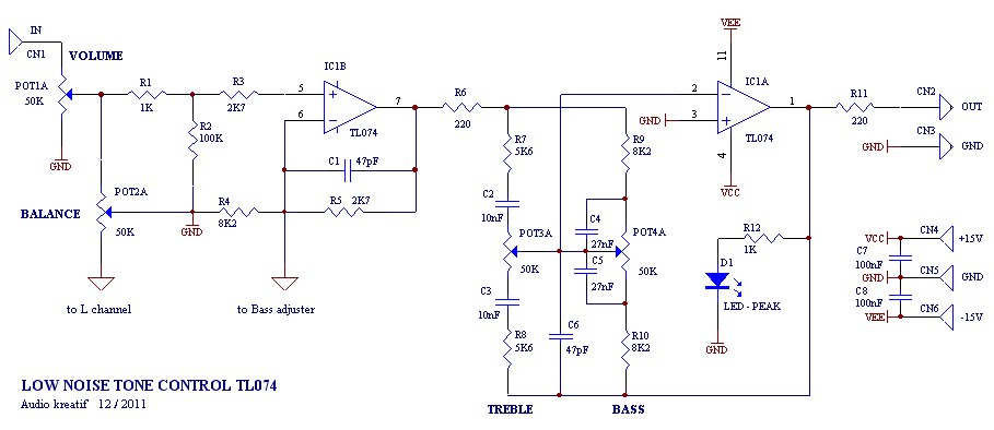
A tone control or pre-amplifier is an amplifier circuit that enhances audio signals. It is important to understand the characteristics, advantages, and disadvantages of various amplifier equipment, as the performance of different amplifiers may not show significant differences. The...
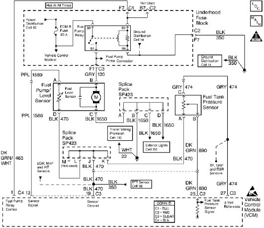
The control module monitors the fuel tank pressure (FTP) sensor signal to detect vacuum decay and excess vacuum during the enhanced evaporative emission (EVAP) diagnostic. The Fuel Tank Pressure Sensor responds to changes in the fuel tank pressure or...
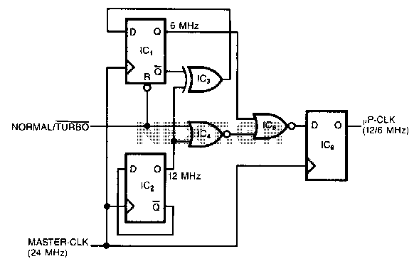
This circuit generates a dual-speed clock for personal computers. It synchronizes asynchronous switch inputs with the master clock to provide glitch-free transitions between clock speeds. The dual-speed clock allows certain programs to operate at a higher clock speed for...
The battery voltage is 1V for a low-frequency amplifying circuit, which can operate with a power supply voltage ranging from 1V to 1.7V, making it suitable for use with small batteries. The circuit provides an output power of 80mW...

The inverting input is maintained at a low level via a 10K resistor when the circuit is powered on but not in use. During measurement activities, including calibration measurements where the input is floating, this resistor is disconnected. The...

The LTC3113 fixed frequency buck-boost DC-DC converter can be utilized to design various power supply circuits that operate with input voltages that are above, below, or equal to the output voltage. The topology integrated into the IC ensures low...