
555 make use of digital amplifier circuit diagram

The Class-D amplifier circuit described is based on the operation of the 555 timer IC, which functions as a versatile multivibrator capable of generating PWM signals. The circuit is designed for audio amplification, taking advantage of the high efficiency and compact nature of Class-D amplification technology.
In this configuration, the input audio signal is connected to pin 5 of the 555 timer. The resistors R1 and R2, along with capacitor C1, are selected to set the frequency of the PWM output to 100 kHz with a 50% duty cycle. This frequency is optimal for audio applications, allowing for effective modulation of the audio signal without significant distortion.
The output from pin 3 of the 555 timer provides a PWM signal that varies in width according to the amplitude of the input audio signal. This relationship is crucial for maintaining audio fidelity, as the width of the pulses directly correlates to the amplitude of the original audio waveform.
To drive a speaker, the PWM signal is passed through an inductor L and capacitor C3, which serve as a low-pass filter. This filtering process smooths the PWM signal, converting it back into an analog audio signal suitable for driving a speaker. The inductor helps to block high-frequency components, while the capacitor assists in smoothing the output, ensuring that the final signal is clean and free of unwanted artifacts.
Overall, this Class-D amplifier circuit using the 555 timer is an efficient and effective solution for audio amplification, providing a compact design with high performance for various listening applications.Also known as digital amplifier Class-D amplifier with small size, high efficiency characteristics. Here are a circuit made easy with 555 Class D amplifier. It is the use of ci rcuit 555 constitute a controllable multivibrator, an audio signal input to the control terminal to obtain a pulse width modulated signal (as shown), to meet the basic requirements for general listening. By the IC 555 and R1, R2, C1 and other components 100KHz controlled multivibrator 50% duty cycle, control the input audio signal terminal 5 feet, 3 feet will get the pulse width of the input signal amplitude is proportional to the pulse signal by L, C3 to answer the call, push the speaker after filtering.
Related Circuits
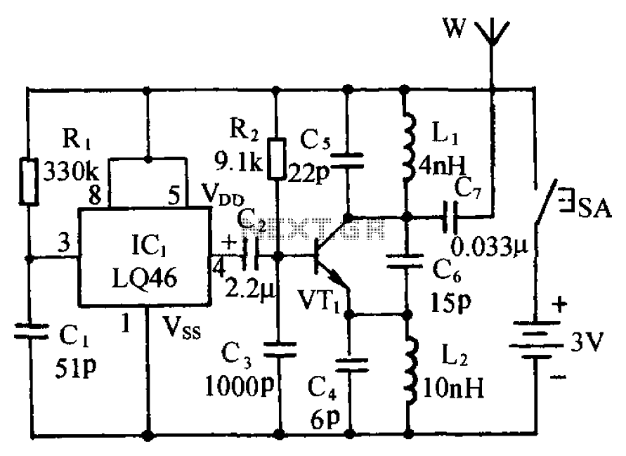
The circuit is presented, consisting of a language and sound circuit FM transmitter. It is simple and easy to manufacture, compatible with ordinary FM radios, allowing for potential listening scenarios and preventive measures. The FM transmitter circuit is designed to...
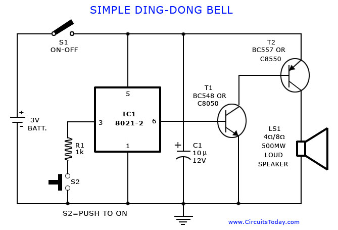
A tone generator circuit, which can be used to create a simple calling bell circuit, is illustrated here. It is constructed using the 8021 integrated circuit (IC), which includes built-in circuitry for producing a "ding-dong" sound. The tone generator circuit...
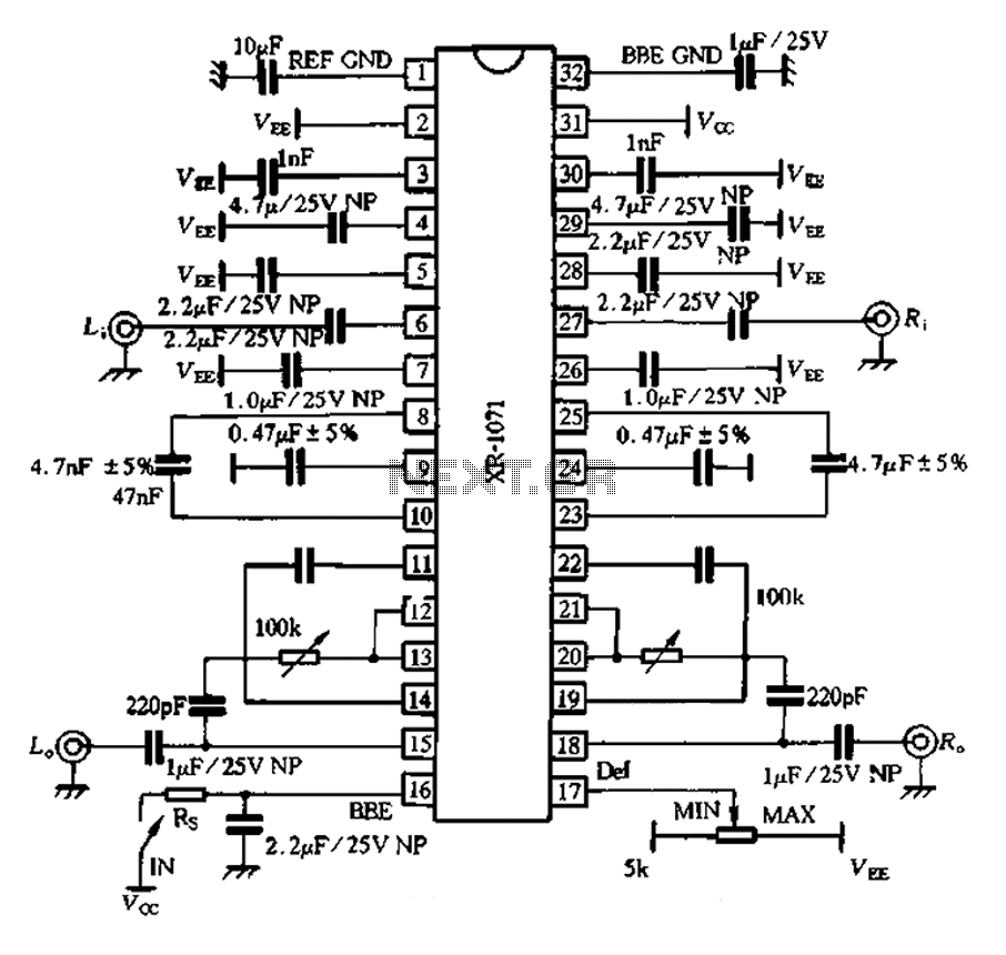
The 1071 touch utilizes audio enhancement technology, introducing a high-resolution two-channel stereo enhancement processing chip designed to improve product performance. It aims to enhance stereo sound systems, allowing various audio sources to exhibit a strong spatial presence. The chip...
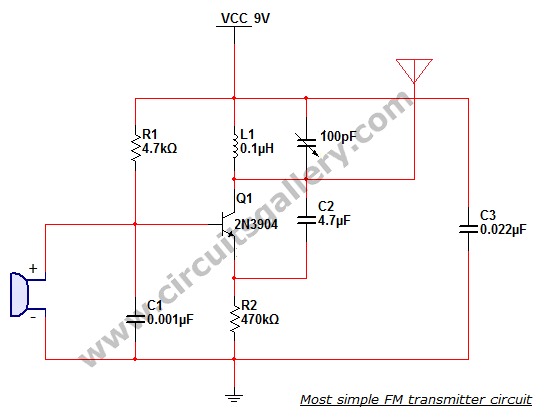
This is the simplest single transistor FM wireless transmitter circuit ever posted in CircuitsGallery. In the field of telecommunications, frequency modulation (FM) transmits information by altering the frequency of a carrier wave based on the message signal. FM utilizes...

The micro ampere meter presented here functions as a DC millivolt meter. It achieves full-scale deflection with a 0.1V input. The current to be measured flows through a known resistance R, and the voltage drop across this resistance is...
The following circuit illustrates a 10.7 MHz RF amplifier and filter circuit diagram. Features include significant capacitances of a power MOSFET. The 10.7 MHz RF amplifier and filter circuit is designed to amplify radio frequency signals while simultaneously filtering out...