
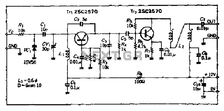
10.7 MHz RF Amplifier And Filter

The 10.7 MHz RF amplifier and filter circuit is designed to amplify radio frequency signals while simultaneously filtering out unwanted frequencies. This circuit typically employs a power MOSFET, which is favored for its high efficiency and ability to handle high-frequency signals. The circuit can be divided into two main sections: the amplifier stage and the filter stage.
In the amplifier stage, the MOSFET operates in the active region, where it amplifies the input RF signal. The gate of the MOSFET is connected to the input signal through a coupling capacitor, which blocks any DC component while allowing the AC RF signal to pass. The drain of the MOSFET is connected to a load resistor, which converts the amplified RF signal into a usable output. Biasing resistors are also included to ensure the MOSFET operates within its optimal range.
The filter stage follows the amplifier and is designed to select the desired frequency of 10.7 MHz while attenuating other frequencies. This is typically achieved using a combination of inductors and capacitors configured in a low-pass or band-pass filter topology. The choice of components and their values is critical for defining the filter's cutoff frequency and bandwidth.
To ensure stability and minimize distortion, feedback mechanisms may be included in the design. This can be done by incorporating a feedback resistor that connects the output back to the input, providing a portion of the output signal to the input, which helps stabilize the gain of the amplifier.
Overall, this circuit is essential in applications such as radio receivers and communication systems, where precise amplification and filtering of RF signals are required for effective signal processing. Proper layout and component selection are crucial to minimize parasitic capacitances and inductances that could affect the performance of the circuit at high frequencies.he following circuit shows about 10.7 MHz RF Amplifier And Filter Circuit Diagram. Features: capacitances of a power MOS-FET become significant, .. 🔗 External reference
Related Circuits
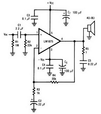
The amplifier circuit can be constructed using the LM1875 power amplifier IC. The LM1875 is a single-chip power amplifier from National Semiconductor. This 20-watt audio amplifier is characterized by low power consumption while delivering high-quality sound suitable for use...
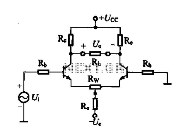
Differential amplifier circuit with four connection methods and characteristics for comparison. The circuit exhibits magnification with a single tube when symmetrical. Additionally, CMRR (Common Mode Rejection Ratio) is adapted from single-ended input to a double-ended output. The differential amplifier is...
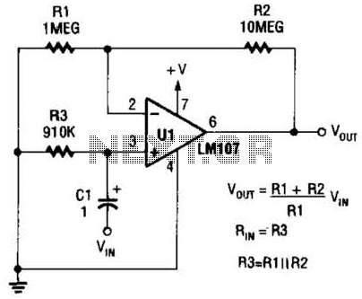
A general-purpose noninverting AC amplifier for audio and other low-frequency applications is presented. Design equations are included in the figure. Almost any general-purpose operational amplifier can be utilized for U1. The circuit configuration features a noninverting amplifier topology, which is widely...
This transmitter is PLL controlled and the frequency is very stable and can be programmed digitally. The transmitter will work from 88 to 108 MHz and the output power is up to 500mW. With minor changes the frequency can...
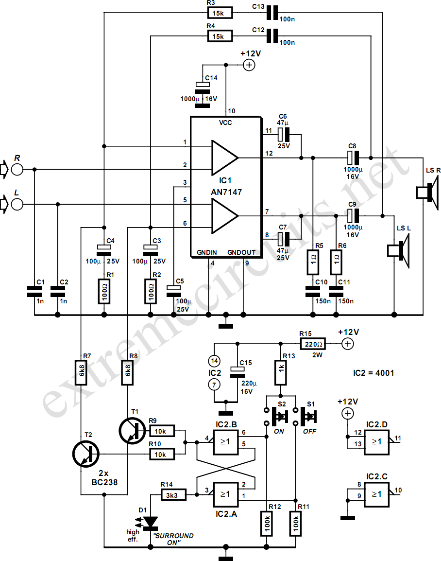
The AN7147 Dual 5.3-watt Audio Power Amplifier from Panasonic is categorized as a replacement type, indicating its anticipated availability in the market for an extended period. When combined with additional components, it can be configured to create a simple...
The Bong circuit is a high-frequency Colpitts oscillator that utilizes a Ge coil (L). It features two heads and is designed for simple production. The frequency of oscillation can be determined, and testing is conducted to ascertain the value...