
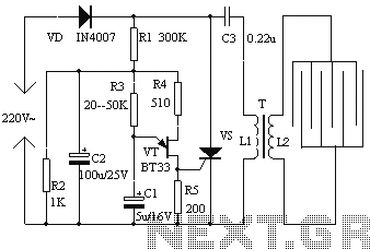
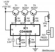
555 Rock lantern controller circuit diagram

The described controller circuit operates primarily as a lighting control system, utilizing a 555 timer in an astable configuration to generate a square wave output. This output controls multiple sets of lights in a sequential manner, creating a visually appealing lantern effect. The 555 timer's configuration allows for easy adjustment of the duty cycle and frequency of the output signal through the variable resistor RP1. The circuit's design ensures that when one set of lights is illuminated, the others are turned off, preventing simultaneous activation and allowing for a clear, distinct lighting sequence.
The use of relays (J1, J2, and J3) in conjunction with transistors (VT1 and VT2) facilitates the high-voltage control of the lights, enabling the safe operation of the 220V lighting system. The inclusion of diodes (D3, D4, and D9) ensures that the circuit remains stable by preventing back EMF that could damage the transistors and other components. The capacitor C3 plays a crucial role in timing, charging to the specified voltage to initiate the next sequence of lights.
The transformer (T), rated at 5VA with a secondary output of 2x12V, is essential for stepping down the voltage to a usable level for the control circuit and the lights. This transformer must be appropriately rated to handle the total load of the lighting system while ensuring safe operation. Overall, this controller design is suitable for applications requiring sequential lighting effects, such as decorative lanterns or stage lighting, and can be tailored to various voltage and power requirements based on the specific components used. As shown, the controller includes a buck rectifier circuit 555 multivibrator, lantern control circuit for ~ 220V, 5W low power parallel control lights or 6 ~ 12V small bulb ser ies rock control. 555 and D3, D4, RP1, C2 composition astable multivibrator, adjust RP1, changing the charging circuit, the discharge time constant, so that alternating square wave of duty ratio 2: 1 When the 3-pin output is low level, the discharge tube discharge within the substrate, 7 feet was low, LED1 bright, J1 pull, the first set of lights lit; 3 feet when the output is high, VT1 conduction, LED2 bright, J2 pull The second group of bright lights, and because J1 released the first set of lights out. At the same time, C3 charge, when C3 charge to 1.3V, VT2 conduction, J3 pull, the third group lantern light.
Since VT2 saturated conduction, D9 clamp, make VT1 off, J2 release, the second set of lights off. Thus, by adjusting the RP1, RP2, so that the three groups equal time lights turn lights, such as lanterns and roll again and again. Transformer T uses 5VA, secondary 2X12V can be.
Related Circuits
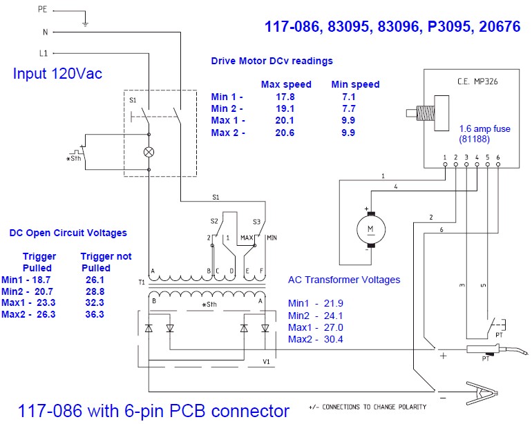
The wire speed DC motor consistently receives approximately 20 volts, irrespective of the switch position on the nozzle handle. The switch has been tested with an ohmmeter and functions properly. Even after disconnecting the switch from the circuit board,...
The electronic fly disinfestation system is a simple and effective device designed to eliminate flies using electrical means. The apparatus, as depicted in Figure 1, operates on 220V mains power supplied directly through a rectifier. It utilizes a relaxation...
This standalone digital thermometer regulates the temperature of a device based on its requirements. It displays the temperature on four 7-segment displays, with a range from 55 to +125 °C. The core of the circuit is the AT89S52 microcontroller,...
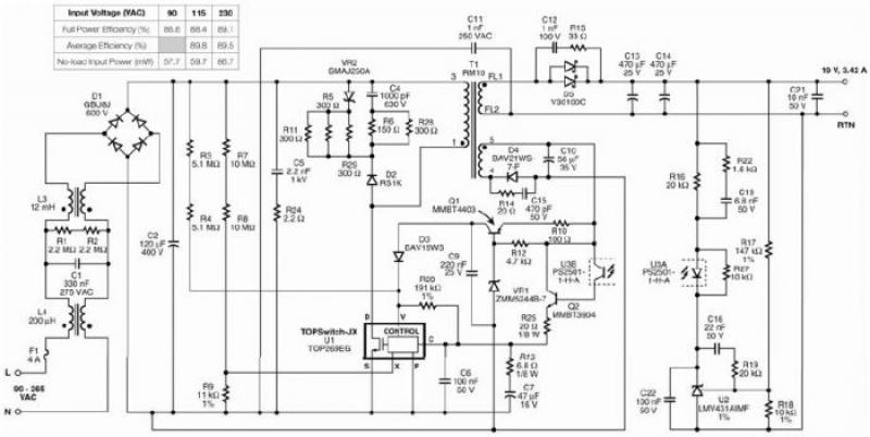
The TOP269EG off-line switcher integrated circuit (IC), designated as U1, can be utilized in a flyback configuration to create a simple and highly efficient power adapter for notebook laptops. The TOP269EG features an integrated 725 V MOSFET and a...
This is a simple home telephone ringtone generator circuit constructed using only a few electronic components. It generates a simulated telephone ringtone and requires a DC supply voltage ranging from 4.5V to 12V. This circuit can be used in...
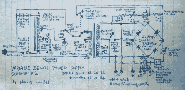
This power supply is able to deliver adjustable center-tapped DC from 0 to about 30 volts, as well as AC directly from the Variac and from the main transformer before the rectifier. What's primitive by today's standard is that...