
Simple home telephone ringtone generator circuit using CD4060B

The circuit utilizes the CMOS IC CD4060 B, which is a versatile binary ripple counter and oscillator. This IC is key to generating the necessary pulse frequencies that drive the transistors and ultimately the piezo buzzer. The three output frequencies allow for the creation of a distinctive ringtone that mimics traditional telephone sounds.
Transistors T1, T2, and T3 serve as amplifiers and switches in this configuration. When the output from the IC is low, the transistors are turned off, and when the output is high, they allow current to flow through, thus activating the piezo buzzer. The resistors R1, R2, and R3 are crucial for limiting the base current to the transistors, ensuring they operate within safe limits while providing sufficient gain.
The piezo buzzer, characterized by its simplicity and efficiency, is driven by the pulsed output from T3. The activation at 20Hz creates an audible ringtone, while the silent intervals help in distinguishing the ringtone pattern. The adjustable presets (VR1 and VR2) provide flexibility in tuning the frequency and amplitude of the output sound, allowing customization based on user preference or specific application requirements.
The circuit's design is compact and efficient, making it suitable for integration into various intercom systems or standalone applications where a simple ringtone generator is required. The use of commonly available components ensures ease of assembly and repair, making this circuit an excellent choice for hobbyists and professionals alike.This is a simple home telephone ringtone generator circuit which is built with applying only several electronic components / parts. It generates simulated telephone ringtone and requires only DC supply with 4. 5V DC to 12V DC voltage. One may possibly use this circuit in ordinary intercom or phone-type intercom. The sound is pretty loud when this c ircuit is operated on +12V DC power supply. Even so, the volume of ring sound can be adjusted. The widely available 14-stage binary ripple counter with built-in oscillator (CMOS IC CD4060 B) is chosen to produce three kinds of pulses, that are obtainable from pin 1 (O11), pin 3 (O13), and pin 14 (O7), respectively. Preset VR1 is fine-tuned to get 0. 3125Hz pulses (1. 6 second low` followed by 1. 6-second high`) at pin 3 of IC1. At the same time, pulses obtainable from pin 1 will be of 1. 25 Hz (0. 4-second low`, 0. 4-second high`) and 20 Hz at pin 14. The three output pins of IC1 are connected to base terminals of transistors T1, T2, and T3 through resistors R1, R2, and R3, respectively.
Transistors T1 through T3 are cascaded in this kind of a way that the positive voltage obtainable at the emitter of transistor T1 is extended to the collector of transistor T3 once the outputs of all of the three stages are low. As a result, transistors T1 through T3 are forward biased for 0. 4, 1. 6, and 0. 025 seconds, respectively and reverse biased for similar durations. Working with a built-in oscillator-type piezobuzzer generates about 1kHz tone. In this particular circuit, the piezo-buzzer is turned on` and off` at 20 Hz for ring tone sound by transistor T3.
20Hz pulses are obtainable at the collector of transistor T3 for 0. 4-second duration. Just after a time interval of 0. 4 second, 20Hz pulses become again obtainable for another 0. 4-second duration. This is followed by two seconds of nosound interval. Thereafter the pulse pattern repeats by itself. Refer the figure that signifies waveforms obtainable at several points including the collector of transistor T3. Preset VR2 could be utilized for adjusting the amplitude of the ring tone. 🔗 External reference
Related Circuits
The curves for a capacitor exhibit significant non-linearity, which can be utilized in circuits to modulate, demodulate, and multiply frequencies. This characteristic is known as non-linear reactance rather than resistance, resulting in minimal energy loss. The charge stored in...
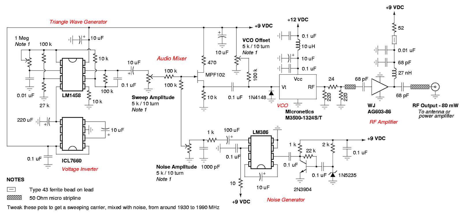
An admirable DIY GSM jammer or cellular mobile phone jammer schematic diagram designed for use with GSM1900, operating within the frequency range of 1930 MHz to 1990 MHz. The GSM1900 cellular mobile phone system is utilized in the USA,...

This circuit combines two or more audio channels into a single channel (for example, converting stereo to mono). It is capable of mixing multiple channels while consuming minimal power. The schematic illustrates two inputs, but additional inputs can be...
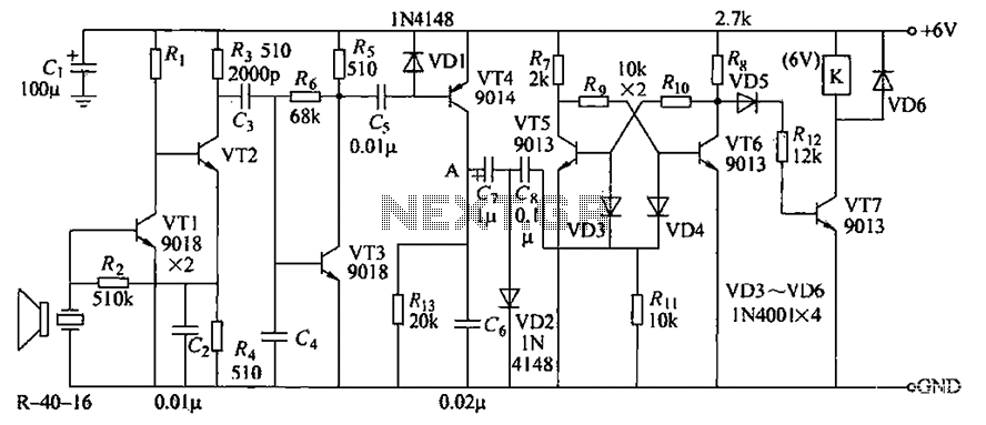
The circuit consists of transistors VT1 through VT7 and other components. Due to the weak signal received from the transmitter, the circuit employs a multi-stage amplifier to enhance the output. This output generates a square wave pulse signal to...

A flashing LED indicates the need to water a plant in a 3V powered circuit. This circuit is designed to signal when a plant requires water. A LED flashes at a specified interval. This circuit operates on a 3V power...
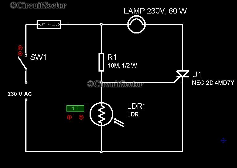
It is very convenient to automatically light a lamp in our absence during the evening when it gets dark. This automatic night lamp circuit can be utilized to illuminate staircase lights, porch lights, etc., automatically using a domestic power...