
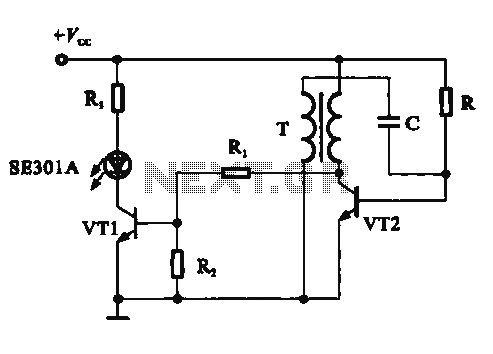
555 Timer Astable Mode Circuit

The 555 timer IC, when configured in astable mode, operates as an oscillator, generating a square wave output. This configuration does not require any external triggering, as it continuously cycles through its high and low states. The frequency and duty cycle of the output signal can be adjusted by changing the values of the resistors and capacitor connected to the timer.
In a typical astable configuration, two resistors (R1 and R2) and a capacitor (C1) are connected in a specific manner. The discharge pin (Pin 7) is connected to the junction of R1 and R2, while the threshold (Pin 6) and trigger (Pin 2) pins are connected to the junction of R2 and C1. When the circuit is powered, the capacitor charges through R1 and R2, and when it reaches approximately 2/3 of the supply voltage, the output at Pin 3 switches from high to low. The capacitor then discharges through R2 until it reaches 1/3 of the supply voltage, at which point the output switches back to high. This cycle repeats indefinitely, producing a square wave output.
The frequency of the output signal (f) can be calculated using the formula:
f = 1.44 / ((R1 + 2 * R2) * C1)
The duty cycle, which defines the proportion of time the output is high versus low, can be determined using:
Duty Cycle (%) = (R2 / (R1 + 2 * R2)) * 100
By selecting appropriate values for R1, R2, and C1, the frequency and duty cycle can be tailored to meet specific application requirements. This versatility makes the 555 timer in astable mode suitable for a variety of applications, including LED flashers, tone generators, and pulse-width modulation (PWM) circuits.As I described in the last step, setting the 555 timer up in astable mode causes it to output a continuous series of pulses. In this circuit, I`ll se.. 🔗 External reference
Related Circuits
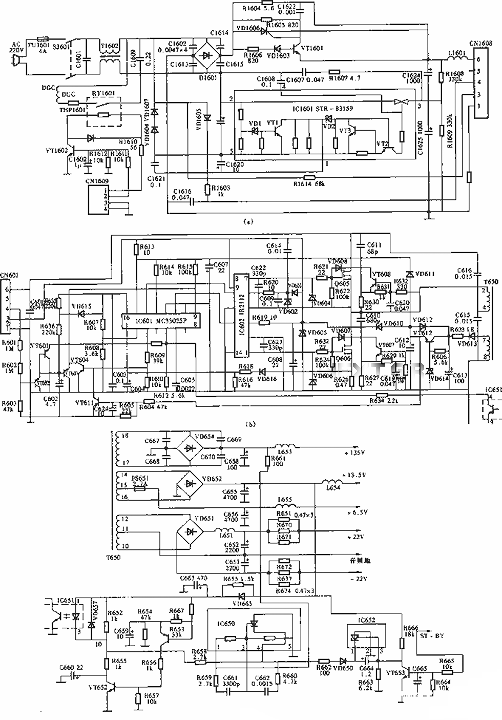
The circuit of the Sony KV-S29MHl (S Movement series) TV switching power supply (SIR a 80145A) consists of three main sections: (A) the power oscillation part, (B) the regulator part, and (C) the output section. The Sony KV-S29MHl TV switching...
This circuit demonstrates a dynamic AC signal level display drive, which can be utilized for audio level display purposes. The AC signal detection and drive control are achieved using the BA6124 integrated circuit, along with five external colored light-emitting...
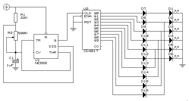
This simple circuit drives six LEDs in a Knight Rider scanner mode. Power consumption primarily depends on the type of LEDs used, especially when utilizing a 7555 (555 CMOS version). The Knight Rider scanner circuit is designed to create a...

This circuit is simple and inexpensive, which is its primary advantage. Although the output power is not high, the audio quality is good due to the TDA1910's low noise characteristics. This circuit is suitable for use as a student...
This circuit is similar to the LED clock using 12 neon indicator lamps instead of LEDs. It operates from 2 high capacity ni-cad cells (2.5 volts) which keep it going for a couple weeks. High voltage (70 volts) for...
The output voltage can be increased easily by placing a resistor in parallel with Ra until it reaches precisely 5.0 V. Switches S1 and S2 are preferably SPDT types with a center position, but three-way rotary switches can also...