
Sony KV-S29MHl TV switching power supply (SIR a 80145A) circuit diagram
")
The Sony KV-S29MHl TV switching power supply utilizes a SIR a 80145A integrated circuit to manage power conversion efficiently. The power oscillation section (A) is responsible for generating the high-frequency AC voltage necessary for the operation of the power supply. This section typically includes components such as a transformer, switching transistors, and associated feedback mechanisms to maintain stability and efficiency during operation.
The regulator section (B) ensures that the output voltage remains stable despite variations in load or input voltage. This is achieved through various control strategies, which may involve pulse-width modulation (PWM) or linear regulation techniques. Components in this section often include operational amplifiers, error amplifiers, and additional filtering capacitors to smooth out the voltage output.
The output section (C) delivers the regulated voltage to the TV circuitry. It is designed to provide adequate current while minimizing ripple and noise, which is crucial for maintaining the performance of the television. This section may also incorporate protective features such as overcurrent protection, thermal shutdown, and short-circuit protection to ensure the reliability and safety of the power supply.
Overall, the design and functionality of the Sony KV-S29MHl TV switching power supply reflect a well-engineered approach to power management, ensuring that the television operates efficiently and reliably under various conditions.As shown in the Sony KV-S29MHl (S movement series) TV switching power supply (SIR a 80145A) circuit; (A) is the power oscillation part; (b) is the regulator part; (c) is the output section.
Related Circuits

The circuit depicted in Figure 3-121 illustrates the key component of an electromagnetic holding brake, which consists of an electromagnetic brake solenoid primarily made up of two parts: the iron core and the shoe brake components. When power is...
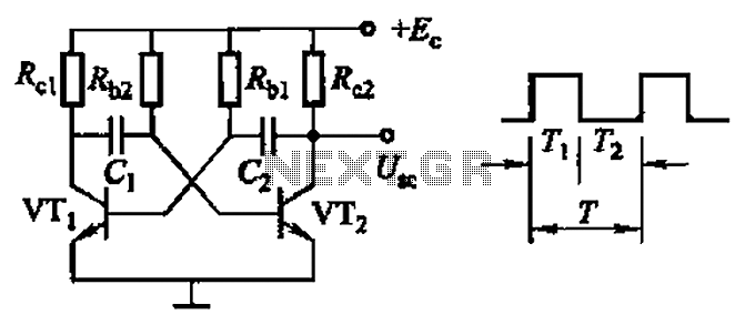
Common non-sinusoidal oscillator circuit, waveform and frequency formula - square wave oscillator - self-excited multivibrator The common non-sinusoidal oscillator circuit, specifically the square wave oscillator, is a fundamental electronic circuit utilized to generate square wave signals. It operates based on...
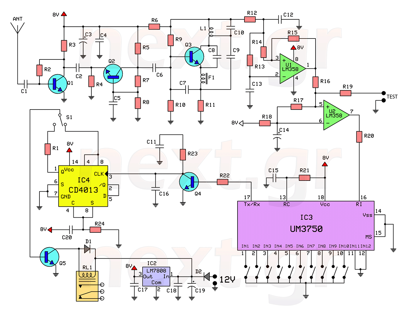
This circuit includes a 2048 radio remote control transmitter and a corresponding wireless receiver that features high reception sensitivity and low power consumption. The combination of these two components provides a highly reliable remote control system, suitable for various...
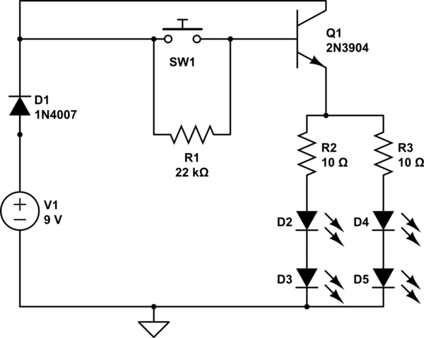
A circuit has been constructed that functions unexpectedly. The circuit utilizes red 5mm LEDs as diodes, a 3904 NPN transistor, and resistors as indicated in the schematic. Logically, pressing the push button normally open (PBNO) should result in the...
This circuit below shows a teleremote circuit that enables the switching on and off of appliances through telephone lines. The teleremote circuit utilizes a telephone line as a medium for controlling electrical appliances from a distance. The primary components...
The following circuit illustrates the electrical circuit diagrams for the Toyota Supra. The diagrams indicate the point at which the power source is received. The electrical circuit diagrams for the Toyota Supra provide a comprehensive overview of the vehicle's electrical...