
555 timer based light seeking robot

The schematic for the robot features a basic structure that integrates various electronic components to facilitate its operation. The primary elements include a microcontroller, which serves as the brain of the robot, controlling its functions and processing inputs from various sensors. The microcontroller is typically connected to power supply circuits that ensure stable operation.
Input devices such as ultrasonic sensors or infrared sensors may be included in the design to enable obstacle detection and navigation capabilities. These sensors provide real-time data to the microcontroller, allowing the robot to make informed decisions based on its environment.
The output components often consist of motors or servos that drive the robot's movement. These actuators are connected through a motor driver circuit, which can handle the current requirements of the motors and provide the necessary control signals from the microcontroller.
Power management is another critical aspect of the schematic. A voltage regulator may be used to ensure that all components receive the appropriate voltage levels, protecting sensitive components from potential damage due to overvoltage.
Connections between components are typically represented with lines on the schematic, indicating the flow of signals and power. Proper labeling of each component and clear representation of the circuit pathways are essential for understanding the robot's functionality and for troubleshooting purposes.
Overall, the schematic diagram serves as a comprehensive guide for assembling the robot, detailing the relationships between components and their individual roles in the overall system.The schematic diagram of this robot is very simple to understand. As I had mentioned earlier I just modified a circuit from on of the books to create.. 🔗 External reference
Related Circuits
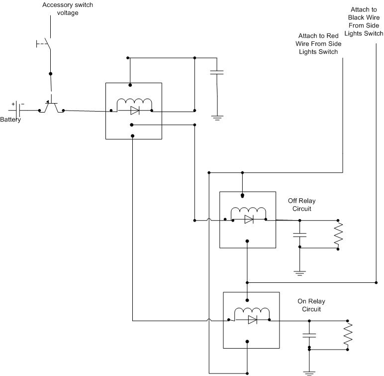
A decision has been made to install daytime driving lights for an Elise vehicle. The intention is to eliminate the need for manually pressing the button on and off repeatedly. The installation of daytime driving lights (DRLs) enhances vehicle visibility...
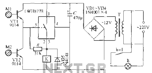
The Rw A77S power system utilizes an integrated circuit fabrication design featuring a dual touch light switch. It employs a transformer (T) for power conversion, a rectifier (VD4), and a capacitor (C) for filtering, resulting in a 12V DC...
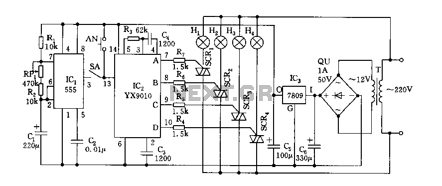
Fantasy lights offer wonderful changes suitable for storage, dance halls, or family holiday decorations. The control circuit is depicted here, which includes a multivibrator control circuit, a thyristor trigger circuit, and a step-down power supply circuit. The AC step-down...
The size of the photoflash charger circuit is significantly simplified and reduced by the Texas Instrument (TI) TPS65552A. This device serves as a photoflash capacitor charger. The TPS65552A is a highly integrated photoflash capacitor charger designed to efficiently charge capacitors...
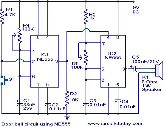
The primary components of this doorbell circuit are two NE555 timer integrated circuits (ICs). When switch S1 is pressed momentarily, the loudspeaker emits a bell tone for the duration determined by the monostable multivibrator configuration around IC1. Pressing switch...
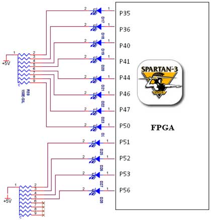
The Spartan-3 board features a traffic light controller utilizing FPGA I/O pins. The traffic light controller card consists of 12 point LEDs arranged in 4 lanes. Each lane is equipped with three LEDs: Go (Green), Listen (Yellow), and Stop...