
Door bell circuit using NE555

The circuit employs two NE555 timer ICs to create a functional doorbell system. The first timer, configured in monostable mode, is activated by pressing switch S1. This action triggers the timer, causing the output at pin 3 to go high, which energizes the loudspeaker for a duration determined by the resistor-capacitor (RC) time constant established by R4 and the timing capacitor. The output duration can be fine-tuned by adjusting the potentiometer R4.
Once IC1's output transitions high, it resets the second timer, configured in astable mode. This configuration allows IC2 to continuously oscillate, generating a square wave output that drives the speaker, producing a bell sound. The frequency of the oscillation, and thus the pitch of the bell tone, can be varied by adjusting potentiometer R5. This flexibility enables users to customize the audible alert according to their preferences.
The circuit's design showcases the versatility of the NE555 timer ICs, which are widely used in various applications due to their reliability and ease of use. For individuals seeking to deepen their understanding of the 555 timer and its applications, several educational resources are available, including reviews of notable books that cover 555 timer circuits and projects in detail. These resources can serve as valuable tools for enhancing knowledge and practical skills in electronics.The main part of this doorbell circuit are two NE555 timer ICs. When some one presses switch S1 momentarily, the loud speaker sounds a bell tone as long as the time period of the monostable multivibrator built around IC1. When the switch S1 pressed, IC1 is triggered at its pin 2 and output pin 3 goes high for a time period previously set by the val
ues of POT R4 and POT R5. When the output ofIC1 goes high it resets IC2 and it starts to oscillate to make a bell sound through the speaker. The IC2 is configured as an astable multivibrator whose oscillation frequency can be varied with the help of POT R5.
By adjusting the values of R4 & R5, modifications on the tone are possible. If you are not familiar with the basics of 555 timer IC, and its applications, you can buy books that will help you get a better understanding from our online store. Totally 3 books have been reviewd in detail along with their authors. You can get their reviews and buy them here:- 3 Great Books to Learn 555 Timer Circuits and Projects 🔗 External reference
Related Circuits
The PIC16C57-RCT is a communication single-chip microcomputer integrated circuit that is commonly utilized in the Qiao Xing series of IC card management telephones. The PIC16C57-RC integrated circuit features a pulse and dual-tone dialing circuit, memory data and clock circuit,...
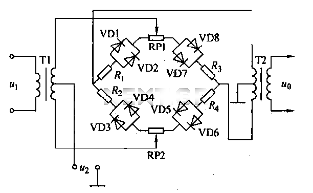
An AM diode ring circuit consists of four diodes arranged in a ring configuration, commonly referred to as a diode ring modulator circuit. This circuit offers significant advantages due to the characteristics of the diodes and the use of...
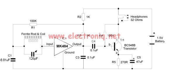
The MK484 AM radio circuit offers a comprehensive solution that includes an RF amplifier, detection, and automatic gain control (AGC) circuit. It requires only a few external components to achieve a high-quality AM tuner. The circuit features an input...
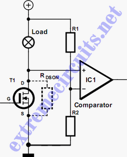
In applications where a MOSFET is used to switch a load, it is relatively straightforward to incorporate short-circuit or overload protection. This can be achieved by utilizing the internal resistance RDS(ON), which generates a voltage drop proportional to the...
Developed as an interface between the General Instruments AY-3-8500-1 TV game chip and the antenna terminal of a TV set. Adjust capacitor C1 to the frequency of an unused channel to which the receiver is set for playing games....
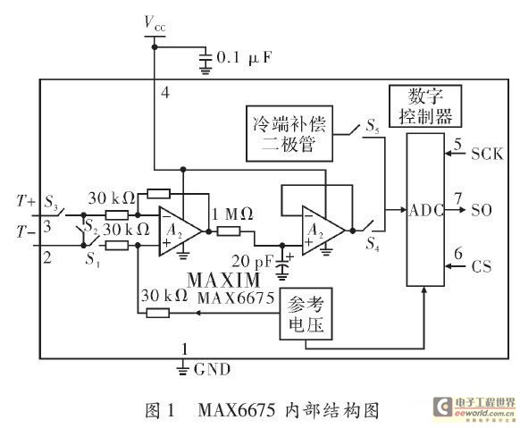
The K-type thermocouple is a commonly used temperature sensor in industrial production and scientific experiments. It can measure temperatures ranging from 0 to 1300 degrees Celsius in various applications, including direct measurements of gas, liquid, and solid surfaces. Its...