
555 timer music instrument

The electronic schematic for this music instrument utilizes a 555 timer in astable mode, generating a square wave output that drives a speaker. The circuit's core components include the 555 timer chip, resistors, capacitors, and the innovative paper and graphite resistor. The paper resistor is created by drawing thick lines with a pencil on a sheet of paper, which varies the resistance based on the contact point of a wire. The integration of a 6.8-kilo-ohm resistor in series helps to set a baseline resistance and ensures the circuit operates within safe limits.
In the first circuit configuration, the 0.1 microfarad capacitor allows for a wider range of frequencies to be produced, resulting in a more versatile sound output. The pencil marks must be carefully drawn to create distinct resistance levels that correspond to musical notes. The second circuit, using a 2.3 nanofarad capacitor, permits the use of thinner pencil lines, which increases the precision of the resistance values and enhances the differentiation between musical notes.
The automatic music player features a mechanical system that feeds a long strip of paper with pre-punched holes, allowing for the sequential activation of musical notes. The wire loops are strategically positioned to align with the pencil marks on the paper, ensuring that only one loop contacts a mark at any given time. This design enables the playback of melodies by pulling the paper through the loops, effectively translating the physical interaction into audible sound. The entire assembly can be further enhanced with additional features, such as volume control and different sound modulation options, making it a versatile and educational project for exploring the principles of sound synthesis and electronic circuitry.A very simple music instrument/keyboard for playing music using a 555 timer chip circuit, a piece of paper and a pencil. To see it in action watch the how-to-make video below. And then I made the much fancier automatic music player in the photo below by making a playing head and a way to feed in a long sheet of paper with the musical notes represented as holes in the paper.
To see it in action watch the how-to-make video below. And then I made this far more robust one, with hand crank, loud speaker and everything. This was made for the 2013 Ottawa Mini-Maker Faire. Click here for full details of this 555 timer music player. Below are drawn the circuits used for the above music devices. The "paper and graphite resistor" refers to a sheet of paper with thick pencil marks drawn on it. This pencil marks acts as variable resistors. In the circuit below you can see it`s wired in series with the 6. 8 kilo ohm resistor. By moving the end of the red wire across the marks, the 555 chip sends different frequencies to the speaker. The two circuits differ in the shape of the pencil marks for the paper and graphite resistor and in the capacitance of one of the capacitors.
In the circuit on the left the capacitor is a 0. 1 microfarad one and on the right it`s a 2. 3 nanofarad one. Using the smaller capacitor allows for thinner lines with higher resistance to be drawn between each rectangular mark for the graphite resistor. The higher resistance makes it easier to make marks that represent different musical notes. In the first circuit the contact is made by touching it anywhere with a wire. You can see this in the circuit diagram on the left above and in the photo below. In the second circuit contact is made as follows and as shown in the photos below. Each rectangular pencil mark represents a different musical note. Contact is made with the marks using one of 11 wire loops. To contact only one mark at a time, holes have been made in a long strip of paper. As the paper is pulled between the wire loops and the pencil marks, one hole in the paper will allow one loop to contact a mark.
When it does, electrical contact is made and the musical note represented by that mark is played. Pulling the paper along, plays a song, in this case the first part of Greensleeves. 🔗 External reference
Related Circuits
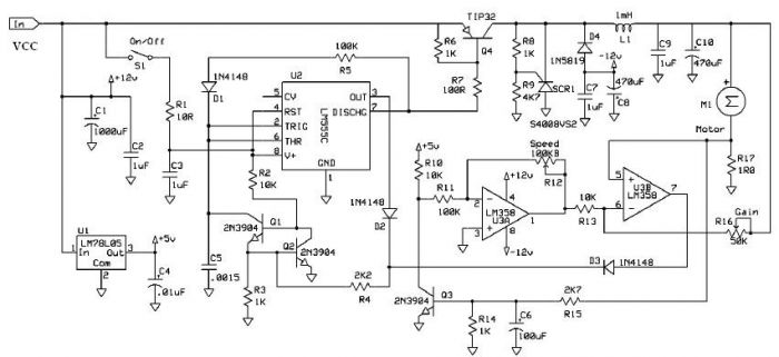
Speed regulation is achieved by monitoring the motor current with resistor R17 and utilizing it as positive feedback to offset motor resistance losses. The gain potentiometer should be adjusted to just below the threshold where motor speed begins to...
This is a short-range light barrier designed for use as an intruder alarm in doorposts and similar applications. The 555 timer in the transmitter oscillates at approximately 4.5 kHz. The short-range light barrier operates by utilizing a transmitter and a...

This differential amplifier utilizes the isolated high-impedance inputs of the CA3420 BiMOS operational amplifier. The input current of the CA3240 is limited to a maximum of 50 pA, allowing for the use of 10-MΩ resistors in series with the...
The circuit below illustrates generating a single positive pulse which is delayed relative to the trigger input time. The circuit is similar to the one above but employs two stages so that both the pulse width and delay can...
The 555 circuit described is a flashing bicycle light powered by four C, D, or AA cells (6 volts). It features two sets of 20 LEDs that flash alternately at approximately 4.7 cycles per second, utilizing the specified RC...
The charger consists of two stages: The first is a capacitive voltage doubler, which uses a 555 timer IC driving a pair of transistors connected as emitter followers, which in turn drive the voltage doubler proper. The doubler has...