
40 LED Bicycle Light Using 555

The described circuit employs a 555 timer configured in astable mode to create a pulsing signal that drives the LEDs. The RC values are crucial for determining the frequency of the flashing LEDs. The resistor R1 (4.7K) and R2 (150K) along with the capacitor (1uF) set the timing intervals for the output signal. The frequency of oscillation can be calculated using the formula:
\[ f = \frac{1.44}{(R1 + 2R2) \times C} \]
Substituting the given values into this formula yields a frequency of approximately 4.7 Hz, which corresponds to the alternating flashing of the LEDs.
The two transistors serve as amplifiers to drive the LED arrays, allowing them to draw more current than the 555 timer can provide alone. This is essential for achieving adequate brightness in the LEDs. The configuration of the transistors should be such that they are connected in a common emitter configuration, allowing for a greater output current while maintaining the switching characteristics dictated by the 555 timer.
The arrangement of the LEDs is such that they are grouped into two sets of 20, with each set connected to the collector of its respective transistor. The series connection of a single LED with the circuit may serve as a current-limiting device, ensuring that the current through the LED remains within safe operating limits.
Overall, this circuit design provides an effective solution for creating a visible and energy-efficient bicycle light, enhancing safety for cyclists during low-light conditions. The use of standard components, such as the 555 timer and common transistors, makes this circuit accessible for hobbyists and engineers alike.The 555 circuit below is a flashing bicycle light powered with four C,D or AA cells (6 volts). Two sets of 20 LEDs will alternately flash at approximately 4.7 cycles per second using RC values shown (4.7K for R1, 150K for R2 and a 1uF capacitor). Time intervals for the two lamps are about 107 milliseconds (T1, upper LEDs) and 104 milliseconds (T2 lower LEDs).
Two transistors are used to provide additional current beyond the 200 mA limit of the 555 timer. A single LED is placed in series with the. 🔗 External reference
Related Circuits
This circuit is a simple 12V DC to 220V AC inverter that produces an AC output at line frequency, specifically 220V AC, or other voltages by selecting transformer T1. The 555 integrated circuit (IC) is configured as a low-frequency...
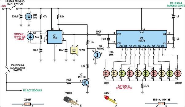
Do you drive an older car without an automatic "lights-on" warning circuit? If so, you have likely accidentally left the lights on and drained the battery on one or more occasions. This headlights reminder circuit will prevent that issue....
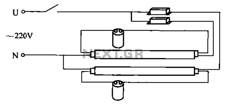
A double tube fluorescent lighting circuit is illustrated. In certain situations, a single tube light may not fulfill the lighting requirements, necessitating the use of double tube lighting. The physical installation is depicted in the circuit of a double...
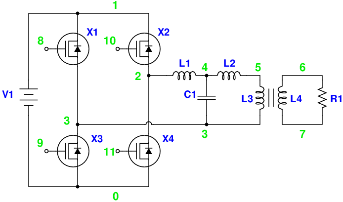
Magic Sinewave Analysis using SPICE and a Simple Inverter Circuit. This document discusses the analysis of a sinewave signal generated by a simple inverter circuit using SPICE simulation software. The inverter circuit is designed to convert a DC input voltage...
This circuit diagram represents a radio-controlled system, commonly utilized in toy car applications for children. The circuit comprises two main components: the transmitter and the receiver circuits. The transmitter circuit generates radio signals through an oscillator circuit built with...
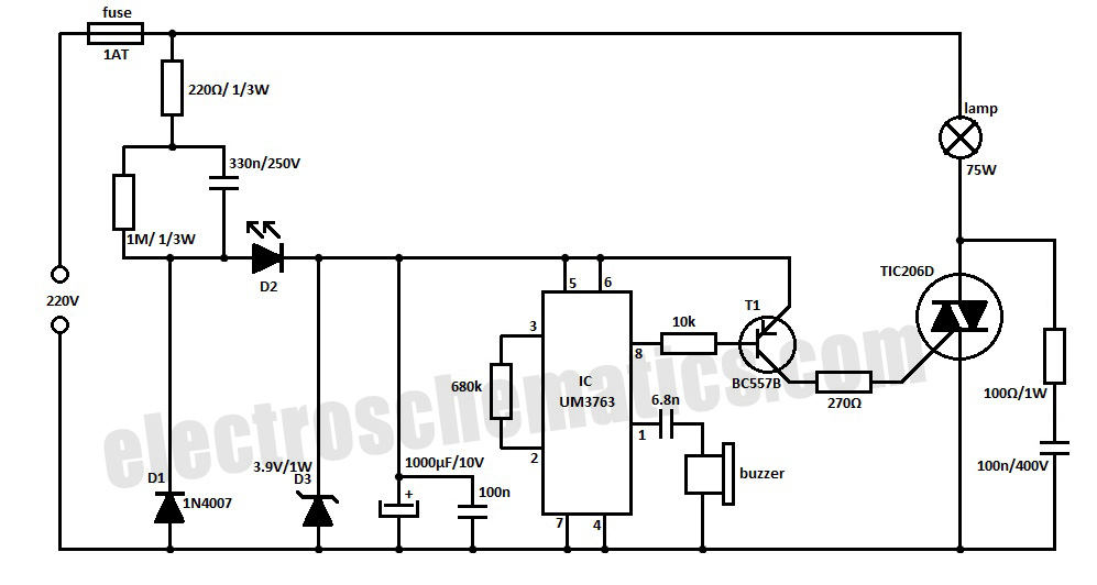
This whistle light switch allows for the control of lighting installations. The primary component of this circuit is the UM3763 integrated circuit, manufactured by UMC. A piezo-ceramic buzzer serves as a microphone, detecting sound frequencies between 1.2 kHz and...