
555 timer reverse polarity 2

A dual power supply configuration, typically indicated as +V and -V, allows for the use of various components, including relays, within electronic circuits. An SPDT relay is a versatile switching device that can connect one common terminal to one of two other terminals, enabling the control of multiple circuits with a single relay. This functionality is particularly useful in applications requiring the switching of power or signals between different paths.
In this context, the choice between an electromechanical relay and a solid-state relay (SSR) should be considered based on the application requirements. An electromechanical relay uses an electromagnetic coil to operate a mechanical switch, offering the advantage of isolation between the control and load circuits. However, it may have limitations in terms of switching speed and durability compared to solid-state options.
Solid-state relays, on the other hand, utilize semiconductor devices to perform switching operations without moving parts, resulting in faster response times, longer lifespans, and reduced noise generation. They are ideal for applications where rapid switching and high reliability are essential.
When designing a circuit that incorporates an SPDT relay, attention must be given to the relay's specifications, such as coil voltage, contact ratings, and switching speed. Additionally, the circuit should include protection components, such as diodes for flyback protection, to prevent voltage spikes from damaging the relay or other components in the circuit. Proper layout practices and component selection will ensure the reliability and efficiency of the relay-based switching mechanism in the overall electronic design.Originally Posted by CDRIVE Thanks for clarifying that. Since you have a dual (+-) supply a SPDT relay will suffice. Do you want a solid state.. 🔗 External reference
Related Circuits
A sawtooth wave oscillator circuit can be implemented using several methods. Here, one design that employs the 555 integrated circuit is presented, along with its schematic diagram. The sawtooth wave oscillator utilizing the 555 timer IC operates in astable mode,...
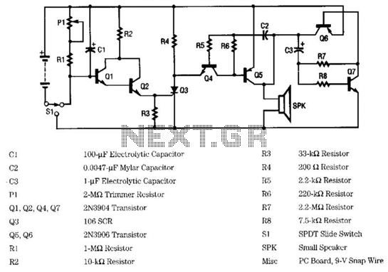
To achieve a lower parts count than the two-transistor multivibrators, two LEDs can be alternately flashed using a 555 integrated circuit configured as illustrated in Schematic 2. A combination of a 2.2kΩ and a 47kΩ resistor is used to...
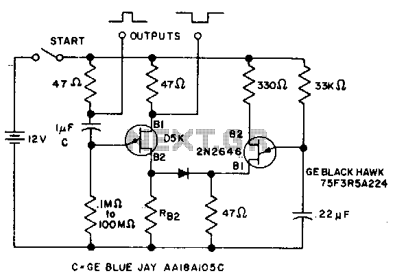
The timer interval begins when power is supplied to the circuit and ends when voltage is applied to the load. The 2N2646 transistor is utilized in the oscillator, which generates pulses to the base of the D5K. This configuration...

Schematic diagram for a dual polarity single channel input voltage to oscillating frequency control. The circuit can be divided into five parts. The reference voltage is established using a TL431 and a 1.2k resistor, functioning as a 2.5V regulator....
This ultra wide range timer utilizes a 555 timer as its core component, along with two 4017 decade counters and a 4020 binary counter that function as frequency dividers, which can be selectively switched in and out. Additionally, the...
The following circuit illustrates a 6/12/24V Lead Acid Battery Charger Circuit Diagram. Features: It is essentially a high-voltage pulse generator. The circuit diagram for a 6/12/24V Lead Acid Battery Charger is designed to efficiently charge lead-acid batteries of varying voltages....