
Simple Astable 555 Timer IC Flasher

The circuit utilizes a 555 timer in astable mode, where it generates a square wave output that alternately activates two LEDs. The frequency of oscillation is primarily determined by the resistor-capacitor (RC) time constant formed by the 2.2kΩ resistor, the 47kΩ resistor, and the 10µF capacitor. The timing interval for the high and low states of the output can be calculated using the formula:
\[
f = \frac{1.44}{(R1 + 2R2) \times C}
\]
where \( R1 \) is the 2.2kΩ resistor, \( R2 \) is the 47kΩ resistor, and \( C \) is the capacitance in farads.
The output from the 555 timer is connected to the anodes of the two LEDs, with the cathodes connected to ground through appropriate current-limiting resistors. This configuration allows one LED to turn on while the other turns off, creating a flashing effect. By substituting the fixed 47kΩ resistor with a potentiometer, users can vary the resistance, thereby adjusting the flashing speed to suit their preferences.
The 10µF capacitor can also be varied to influence the timing characteristics of the circuit. Larger capacitance values will result in longer flashing intervals, while smaller values will increase the frequency of the flashing.
To enhance the visual effect of the flashing LEDs and simulate a police car light pattern, additional circuitry can be introduced. This may involve using additional 555 timers or other timing circuits to create a more complex flashing sequence. The goal is to create a pattern that alternates quickly between the two LEDs, possibly incorporating a third LED for a tri-color effect typical of emergency vehicles.
In conclusion, this simple LED flasher circuit using a 555 timer is an excellent project for beginners, offering opportunities for experimentation and modification to achieve various lighting effects.For a lower parts count than the 2 transistor multivibrators, 2 LEDs can be alternately flashed with a 555 integrated circuit configured as shown in Schematic 2. I chose the combination of a 2K2 and a 47K resistor to determine the oscillation frequency along with the 10 uF capacitor connected to pins 2 and 6.
You can practically change the (R Spee d) 47K value to between 10K and 100K or more. Greater resistance = lower speed. You may also wish to connect up a 100K or so potentiometer instead of the 47K resistor for a variable speed version. Additionally, the 10 uF capacitor value can be changed. Feel free to experiment. Although, alternately flashing LEDs is great for the beginner to electronics, the basic one ON, one OFF circuit gets boring quickly.
In the next section, we will try to improve the look and try to approximate a flash like a police car (within limits). 🔗 External reference
Related Circuits
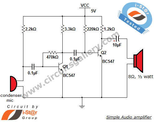
This circuit diagram is a simple and effective design for amplifying weak signals from a capacitive condenser microphone. It is suitable for sound sensing applications and various automatic robotic sensors. While a more complex audio amplifier circuit using the...

The QAMI5516 is an integrated demodulator and decoder solution designed for digital cable receivers, capable of handling compressed video, audio, and data services. This QAM demodulator executes intermediate frequency (IF) to MPEG-2 block processing of QAM carriers. The resulting...
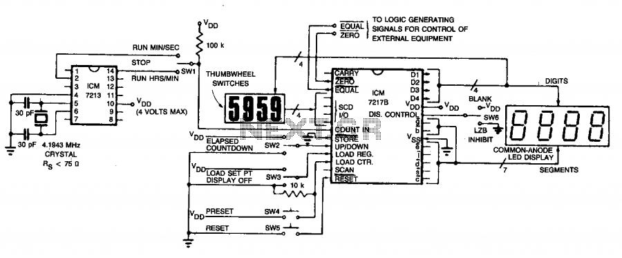
The circuit employs an ICM7213 precision timebase generator with a frequency of 4.1943 MHz, which is utilized for generating pulses that are counted by an ICM7217B counter. Thumbwheel switches are incorporated to allow the user to input a starting...
Construct a basic audio amplifier utilizing transistors. While integrated circuit (IC) designs are available for this purpose, the intention is to use transistors to gain practical knowledge about their amplification capabilities. The article "Amplifier Basics - How Amps Work...
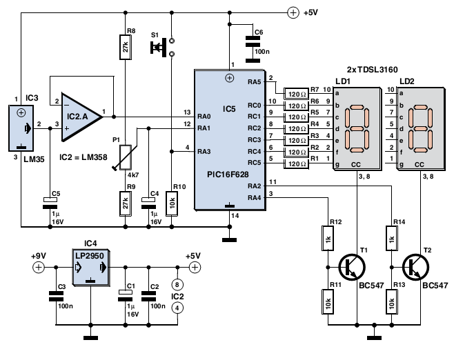
The device is user-friendly and consumes minimal current, allowing it to operate throughout the battery's shelf life. It employs a standard LM35DZ sensor (IC3) whose analog output voltage is buffered by an LM358 (IC2A). The voltage is processed by...
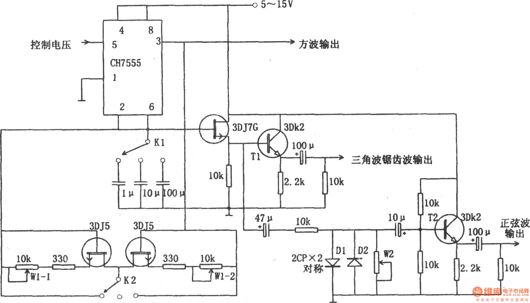
The chart illustrates a function generator circuit utilizing a 555 timer. This circuit includes a CH7555 timer along with several transistors and RC components. It is capable of generating triangle waves, square waves, sine waves, sawtooth waves, and square...