
555 Timer To Control Motors

The 555 timer integrated circuit (IC) is a versatile component utilized in a multitude of applications, particularly in timing, pulse generation, and oscillator circuits. In the described project, the 555 timer is employed to control a motor's operation through a timing mechanism. The IC's configuration allows for a delay of 40-50 seconds, which can be achieved by adjusting the resistor and capacitor values connected to the timer.
To effectively control the motor, a transistor is necessary to amplify the current since the 555 timer's output is limited to around 100 mA. The recommended NPN transistors, such as the BFY50 or 2N3055, are suitable for this application. The transistor's base should be connected to pin 3 of the 555 timer, while the collector connects to the positive supply voltage (+V), and the emitter connects to the motor. A diode should be placed across the motor terminals to protect against back EMF generated when the motor is switched off, with the cathode connected to the positive terminal.
In cases where the motor's current demand exceeds 1.5 A, a Darlington pair configuration may be necessary to ensure adequate current handling. It is critical to consider the starting current of small DC motors, which can be significantly higher than the running current, often ranging from 10 to 20 times more, depending on the load and torque requirements.
The 555 timer circuit should be constructed first on a breadboard to validate its functionality before transferring it to a printed circuit board (PCB) for permanent installation. This approach allows for troubleshooting and adjustments without the constraints of soldering components.
In addition to the basic timing function, the 555 timer's output should be protected against voltage spikes, especially when driving inductive loads like motors. This can be achieved by adding a reverse polarity diode in parallel with the motor windings, ensuring that any voltage spikes do not damage the timer or other components.
The historical context of the 555 timer highlights its introduction by Signetics in the 1970s, which has led to its widespread adoption due to its low cost and ease of use. The 555 timer remains a staple in electronic design, particularly for hobbyists and students, due to its straightforward application in timing circuits and pulse-width modulation tasks.I am a mechanical engineering student, and for a part of my design project I wish to use a timer as so the motor switches off about 40-50 seconds after activation. The 555 timer chip is a rectangle with a indented o on the top, i assumed this was equivalent to the cutout semi circle (please tell me i don`t have the chip the wrong way around).
With the chip package in the orientation you describe, pin 1 is at the upper left, pin 2, 3, and 4 are below it, in order, on the left side. Proceeding around the package in an anticlockwise direction, pin 5 is at the lower right, then 6, 7, and 8.
Pin 8 is opposite pin 1, at the upper right corner of the package. I have just had a look at the circuit and to run a motor you need a transistor to handle the current, it is most likely you have burned out the internal device. It can only handle 100ma or so. You need a power device and it should have the base connected to pin 3 then the collector to +V and emitter to the motor put a diode across the the motor terminals cathode to +V terminal with a 0.
1uF cap ceramic 32v for up to 12V supply. Use an NPN Tr. BFY50 or 2N3055 TIP3055 with a heat sink. You may need to use a Darlington configuration if the current is above 1. 5 amp for the motors, remember the starting current for a small DC motor can be 10 to 20 times is running current, and any load will demand a proportion more than no load. It depends on the torque required. I hope this helps you out some. There`s them that knows and them that just thinks they know, whitch are you Stir the pot and see what rises up.
I have catalytic properties I get a reaction going. Here it is suggested a NPN power transistor. Be sure the output from 555 has also reverse diode protection as output from power transistor (another diode reverse polarity connected in parallel to motor windings (In to motors). Electronic / semiconductor devices are easily damaged by voltage spikes produced in inductive (motor windings) load switching circuits.
Proper student`s project should have at least two stages: the circuit assembled on breadboard and second (final after successful tests) soldered on PC board. The 555 timer was introducted by Signetics in the 1970s and is nearly ubiquitous in its application where simple timing circuits, oscillators, pulse-width modulators, and so forth are required.
It is very inexpensive and is still hugely popular with electronics enthusiasts. Here are a few links to web pages dedicated to this chip. Be sure to copy and paste the entire address into your brower`s address bar (my apologies for not making these hot links, but I`m using MacIntosh Safari which cripples CR4`s message editor (no italics, bold and underline, spell-checker, links, pics, etc. , and it eats whitespace so that paragraphs, bulleted lists, etc. , are rammed together into one piece of monolithic text). objectid=6375&objecttype=THREAD&c=47647 AND AND. This should get you started. -e its my first time here. this is interesting. i m only a pilot and i dont have much knowedge in electronics is just a Hobby. but my strenger designed circuits are alwys to sutisfy my needs. like. i like that curcuit of Mr. Ghuru. using 2N3055. there fore forced to register just now, (however i m off topic a bit) i got a circuit that have a solenoid to alter flux of a permanent magnet in a soft iron core material with squre wave +/- altenating 1 Amp, current.
so to have a variable frequency range from 40Hz to 100hz i decided to use 555 and followed by dual 4027 flip flop of which (j, k, Clock) joined together so i decided one output of flip flop to a H brigde and other output to a second input of H brigde. to have a altenating current so i want to asking if ths H-bridge my torelate those frequeny. i hope it may work and any delay to leg out my expected result. It`s a model of the Starship Enterprise NCC-1701A from the movie and to make it more interesting I decided to add lights and the ones like the anti-collision strobes, navigation lights, warp drive etcetera need to flash and at first glance a 555 timer would be the way to go.
However, that would involve having fixed patterns of flashes that once wired in could not be altered so I decided to finally bite the bullet and figure out how to use microcontrollers. Some time back I purchased a PICkit2 from Microelectronics that comes with a small prototyping board.
16F690 microcontroller and USB programmer that can be used to download and program the microcontrollers. It took a couple of weeks (closer to a couple of months) to get up to speed and find the software that works best for me, but in the end I will most likely never use anything more than a microcontroller in any of my electronic designs.
Basing your electronic designs around microcontrollers rather than discrete components may sound like overkill but the added flexibility, simplicity, cost, ease of use etcetera makes the use of microcontrollers by far the best solution for the average hobbyist electronic guru regardless of what you are trying to do. It also means that you can change the way your electronic device works by reprogramming the microcontroller thus making it virtually idiot proof.
Not that much really. Once you get your head around what they are capable of (which is pretty much anything you could imagine) it`s a pretty simple step to design a circuit and program the microcontroller to do what you want. Here are some links to the items you will need to get going. Microcontroller: First off you need to find a microcontroller that will do what you want. For med this is the PIC16F690 which has up to 18 programmable IO ports. If you buy them in bulk like I do (batches of 20) then they are actually cheaper than a standard 555 timer chip and a couple of million times more useful.
Programming Unit: Next up you will need to invest in a programming unit. This is basically an interface that goes between your computer and the microcontroller that enables you to download the program you have written onto the microcontroller. You can build one of these yourself, usually utilizing a microcontroller, but I would recommend using a ready made one.
In my case that`s the PICkit2 from Microchip (see image below) that can be purchased from Microchip for US$49. 99. Compiler: Microcontrollers need to be programmed utilizing what is referred to as machine code. Basically this is a series of instructions that the processing core of the microcontroller executes. Now you can write programs directly in machine code, but I would not recommend going down this path unless you have previous experience in writing machine code.
Instead you can use a compiler that can take complex instructions that then translates them and generate the machine code that the microcontroller can understand and run. Like the programming unit the title . 🔗 External reference
Related Circuits
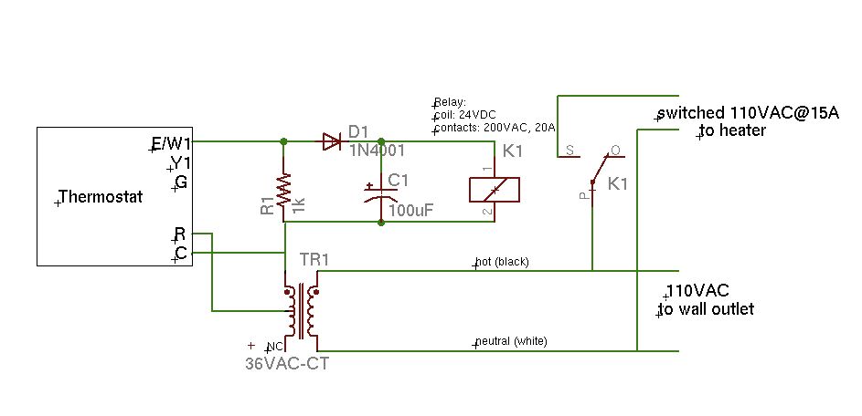
A basic schematic of the circuit is presented, marking the initial experience with Eagle software. It is important to note that only the W1 output of the thermostat is utilized, while C serves as the common connection. The schematic outlines...
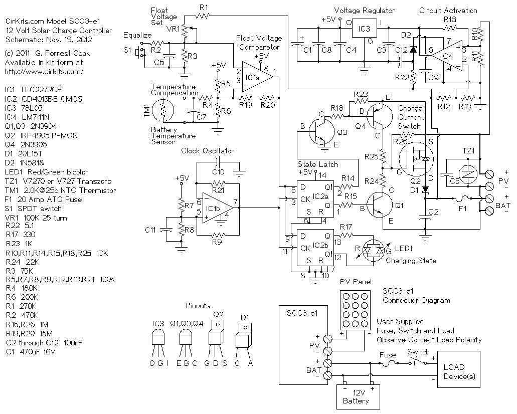
The SCC3 is a solar charge controller. Its function is to regulate the power flowing from a photovoltaic panel into a rechargeable battery. It features easy setup with one potentiometer for the float voltage adjustment, an equalize function for...
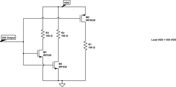
A variable frequency, variably duty cycle 555 configuration is set up in astable mode. A set of potentiometers is utilized to achieve a wide range of control. The output is functioning well; however, there is an issue. The circuit...
Twelve LEDs can be arranged in a circle to represent the twelve hours of a clock face, while an additional twelve LEDs can be arranged in an outer circle to indicate five-minute intervals within the hour. Four additional LEDs...
Here is a handy gadget for testing of infrared (IR) based remote control transmitters used for TVs and VCRs etc. The IR signals from a remote control transmitter are sensed by the IR sensor module in the tester and...
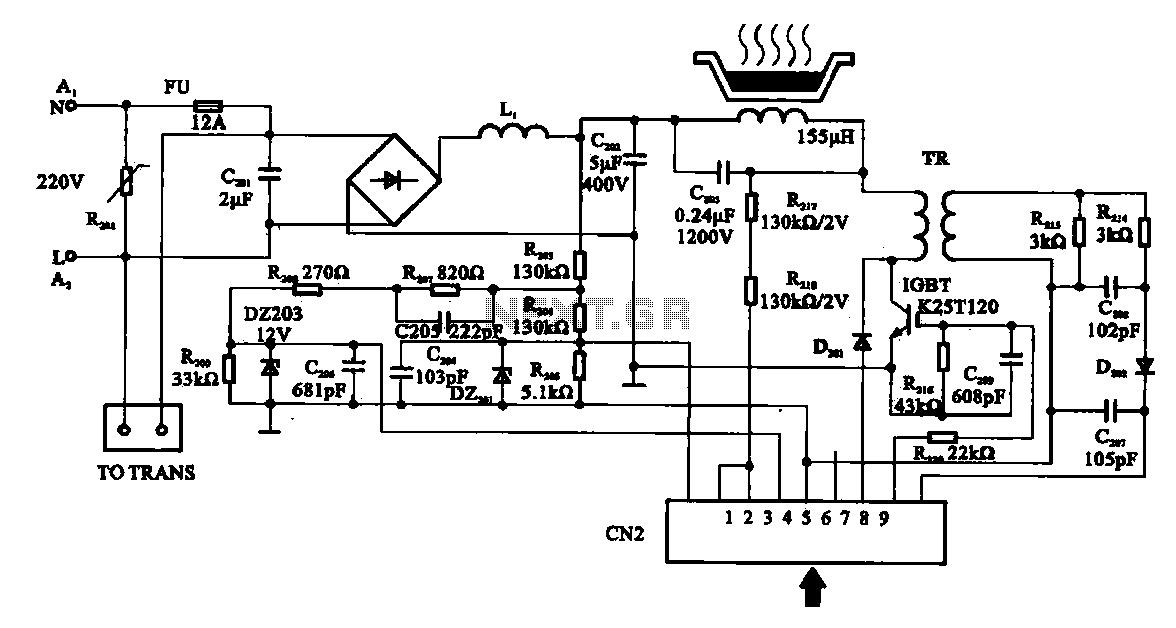
Cooker detection control circuit. The control circuit is designed for testing cookers. The inductance coil disc lesion typically measures around 150 µH. The stove plate coil and capacitor resonate with device C203. When resonating, the voltage generated across C203...