
555 tracking transmitter
The 555 tracking transmitter circuit operates using the 555 timer in astable mode, generating a continuous square wave output that modulates the frequency of the FM transmitter. The output frequency can be adjusted by changing the values of the resistors and capacitors connected to the 555 timer, allowing for fine-tuning of the desired transmission frequency within the FM band. The 2N2222 transistor acts as the amplifier for the RF signal, providing sufficient power to drive the antenna.
Inductor L1, with its specific winding configuration, plays a crucial role in determining the resonant frequency of the transmitter circuit. The 2 turns of #24 wire create a simple inductor that, in conjunction with the trimmer capacitor, allows the circuit to be tuned accurately to the desired frequency. The trimmer capacitor TR enables precise adjustments to the circuit's resonant frequency, ensuring optimal performance and compliance with FM transmission standards.
The choice of antenna is also critical for achieving the maximum transmission range. A 75 cm vertical wire antenna is ideal for effective radiation of the RF signal. The height and orientation of the antenna significantly influence the transmission distance; therefore, positioning the antenna vertically is recommended. Using a shorter antenna will result in a decreased range due to the reduced effective radiating area.
Powering the circuit with 4.5-volt batteries ensures that the 555 timer and the 2N2222 transistor function correctly, as both components are designed to operate efficiently within this voltage range. This flexibility allows the circuit to be powered by various battery types, making it a versatile solution for portable applications. Overall, this 555 tracking transmitter circuit is an excellent project for those interested in exploring FM transmission and radio frequency applications.The schematic shown here is a circuit of a 555 tracking transmitter. 555 is a famous versatile IC used in many electronic projects. In the below mentioned circuit this IC is used to generate a tone which will be transmitted through the FM transmitter circuit which is built around the 2N2222 transistor. The circuit can be tuned between 103 to 108 MHz and will transmit at a distance of 100m. L1 is equal to 2 turns of #24 wire on 5mm form, and TR is equal to 1 to 30 pf trimmer capacitor. Antenna can be a 75cm wire, for full range keep the wire vertical, or you can also use small 6 or 12 inch wire as antenna but the range will become half or less. The circuit can be operated with 4. 5 volt batteries of any type. 🔗 External reference
Related Circuits
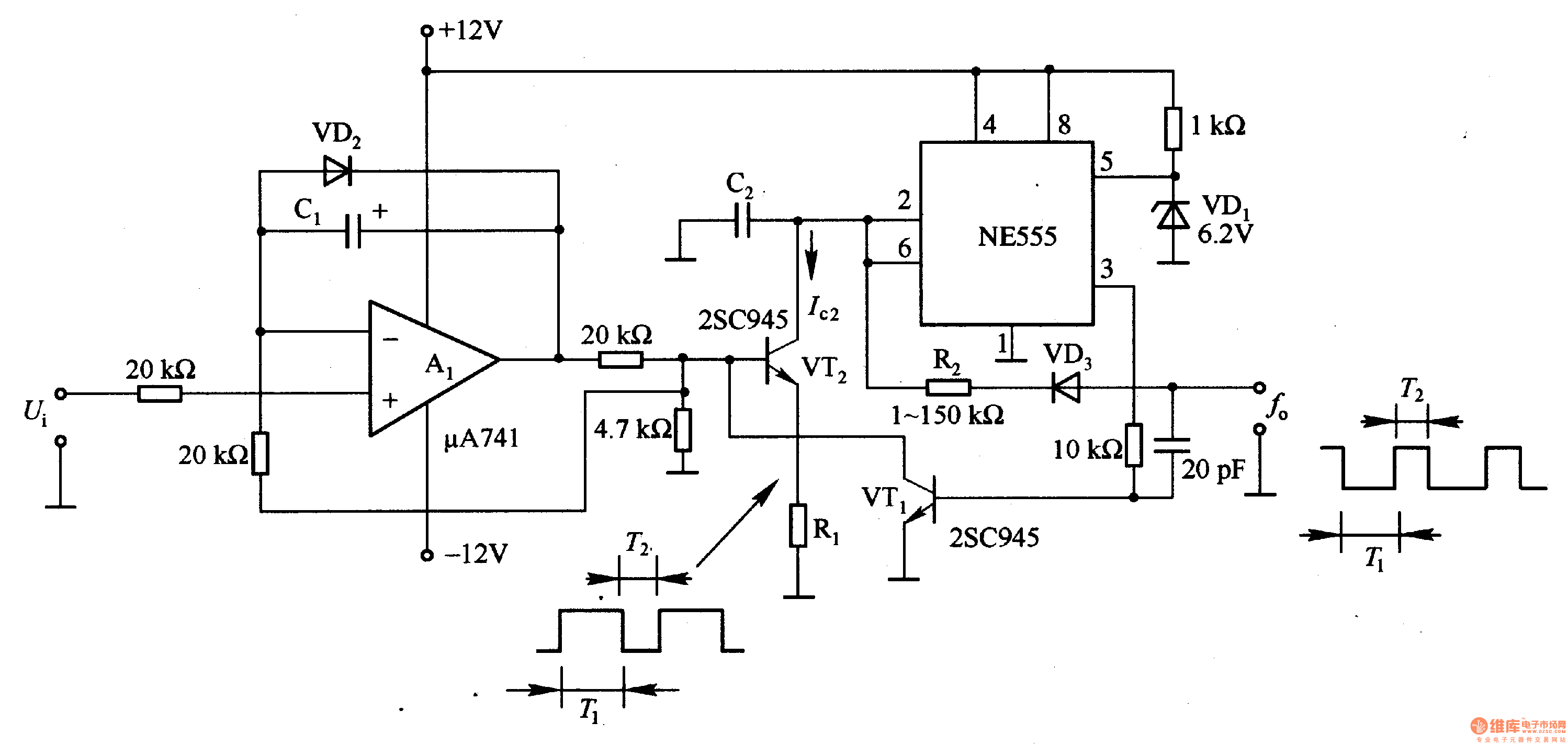
In the circuit, the oscillation frequency of the NE555 is controlled by VT2. When the output at pin 3 is low (during the T1 period), VT1 stops conducting, and VT2 begins to conduct with a current Ic2 flowing through...
On astable multivibrators, the duty cycle is typically fixed unless a potentiometer is incorporated. However, even with a diode in parallel with resistor R2, the duty cycle will only be less than 50%. To initiate a new thread, one...
This UHF transmitter is designed for low power applications such as remote controls for garage doors, operating systems, and wireless alarms. This UHF FM transmitter is equipped with... This UHF transmitter operates within the Ultra High Frequency (UHF) band, which...
The image on the left depicts a high-quality radio transmitter designed for the AM broadcast band. This transmitter operates legally with "micro-power," meaning it will not achieve long transmission distances; however, it maintains stable frequency and excellent fidelity, unlike...
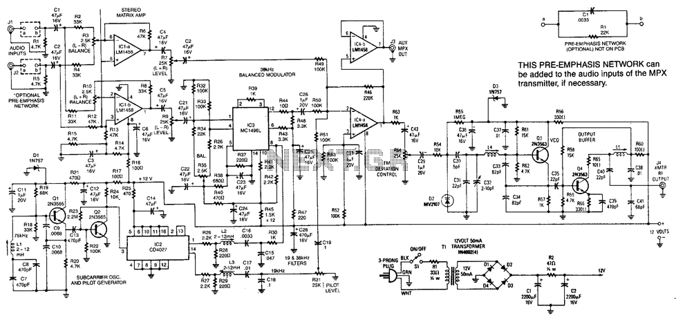
This transmitter has a range of up to 100 feet. It generates a complete multiplex stereo signal and is useful for cordless headphone applications in which an inexpensive socket stereo receiver can be used. It can also be used...
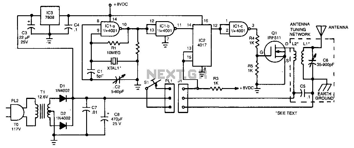
The crystal oscillator utilizes two sections of IC1, a 4001 quad 2-input NOR gate, representing a standard and reliable design. The oscillator generates a 1.85-MHz square-wave output that feeds into IC2, a 4017 divide-by-10 counter. The count enable and...