
555 Voltage Doubler Relay Driver

The relay driver circuits described are designed for applications requiring the control of relays with higher coil voltage ratings than the supply voltage (Vcc) available in the circuit. These circuits employ innovative techniques to ensure reliable operation despite the increased voltage requirements.
The primary components of the relay driver circuit typically include a transistor or MOSFET that acts as a switch, a diode for flyback protection, and the relay itself. The circuit is powered by a voltage supply (Vcc), which is lower than the relay coil voltage rating. The transistor is used to amplify the control signal, allowing it to manage the higher voltage required to energize the relay coil.
When a control signal is applied to the base (for bipolar transistors) or gate (for MOSFETs) of the transistor, it turns on, creating a path for current to flow through the relay coil. This current generates a magnetic field strong enough to pull in the relay armature, connecting the normally open contacts and allowing current to flow through the load connected to the relay.
To safeguard the circuit from voltage spikes generated when the relay is deactivated, a flyback diode is placed in parallel with the relay coil. This diode provides a path for the inductive kickback current, protecting the transistor from potential damage due to high voltage transients.
These relay driver circuits are particularly useful in applications where control signals are limited to low voltages, yet there is a need to control devices that operate on higher voltages. This capability enhances the versatility and reliability of relay-based control systems in various electronic applications.These novel relay driver circuits have the ability to pick up a relay with a coil voltage rating equal to double Vcc. After pickup, the relay armature is h.. 🔗 External reference
Related Circuits
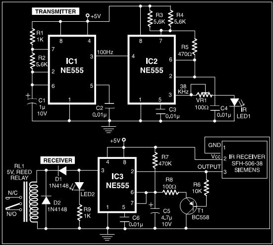
A simple circuit diagram illustrates a schematic for a remote control system, which consists of two parts: the transmitter and the receiver. The transmitter circuit is controlled by an NE555 integrated circuit (IC) and operates by detecting the emitted...
This project was begun as a means to charge and cycle NiCad batteries but has become a versatile tool for experiments requiring either a controlled voltage up to +30V and/or a current of +/- 2.5 Amps. If all you...
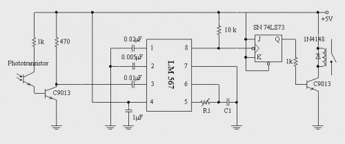
This post discusses a proximity detector circuit primarily utilizing the NE555 integrated circuit (IC). The circuit is designed for burglar alarms based on beam interruption, with the advantage that the transmitter and receiver are contained within the same enclosure,...
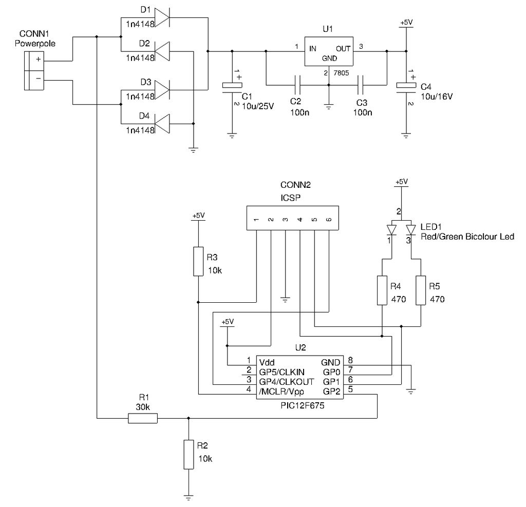
This is a compact device designed for amateur radio (HAM) enthusiasts, utilizing Powerpole connectors to interface HAM equipment with an unidentified power supply that also features Powerpole connectors. The device functions as an essential accessory for HAM radio operators,...
A thermistor is utilized in the circuit for heat sensing, while two 5K variable resistors are incorporated to calibrate the circuit for activating the relay at the desired temperature. The inclusion of a 1N4007 diode across the relay serves...
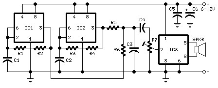
The following diagram is the schematic diagram for a car horn circuit, which can be utilized for car modifications. Components List: R1 = 68K, R2 = 2K2, R3 = 56K, R4 = 3K3, R5, R6 = 4K7, R7 =...