
5W 80M Cw Transceiver

The transceiver circuit is designed to facilitate efficient communication by integrating a three-stage transmitter and a direct-conversion receiver. The transmitter's oscillator, Q1, plays a pivotal role in generating the RF signal, with its frequency being precisely controlled by crystal X1. This crystal not only stabilizes the transmitter's frequency but also acts as the local oscillator for the receiver, ensuring that both sections of the transceiver operate in harmony.
Buffer transistor Q2 is responsible for driving the final amplifier, Q3, which is capable of delivering an output power of around 5 watts. This output is sufficient for effective communication over a variety of distances. The B+ lead, which supplies power to these critical stages, is keyed to prevent unwanted transmission and to ensure that the circuit operates only when intended.
The receiver section is comprised of a mixer (Q4) that combines the incoming RF signal with the local oscillator signal from X1, effectively down-converting the frequency. The subsequent high-gain amplifiers, Q5, Q6, and Q7, amplify the audio signal extracted from the mixer. The output from Q7 provides the audio signal that can be further processed or sent to a speaker for audible output.
In the transmit mode, Q5, Q6, and Q7 are configured to function as a sidetone oscillator, allowing the operator to hear their own transmitted signal, which is crucial for ensuring clarity and proper modulation during transmission. The system incorporates a 6PDT switch to facilitate seamless switching between transmit and receive modes, enhancing the usability of the transceiver in various operational scenarios. This design emphasizes reliability and performance, making it suitable for a range of communication applications. This transceiver has a 3-stage transmitter and a direct-conversion receiver. Ql is the transmitter"s oscillator, an d the frequency is controlled by XI, which also serves as the receiver local oscillator. Buffer Q2 drives final amplifier Q3 to about 5 W output. The B+ lead to these stages is keyed. The receiver consists of mixer Q4 followed by high gain amplifiers Q5/Q6/Q7. The audio signal appears at the secondary of Q7. In the transmit mode, Q5/Q6/Q7 serve as a sidetone oscillator. A 6PDT switch is required for the T/R switching.
Related Circuits
During a 50MHz SSB-QSO, my friend JE3TXU/1 (Mr. Haraguchi) mentioned that he had created a very compact 50MHz transceiver. I suggested that he should share this information in the Japanese CQ magazine. Additional details can be found in a...
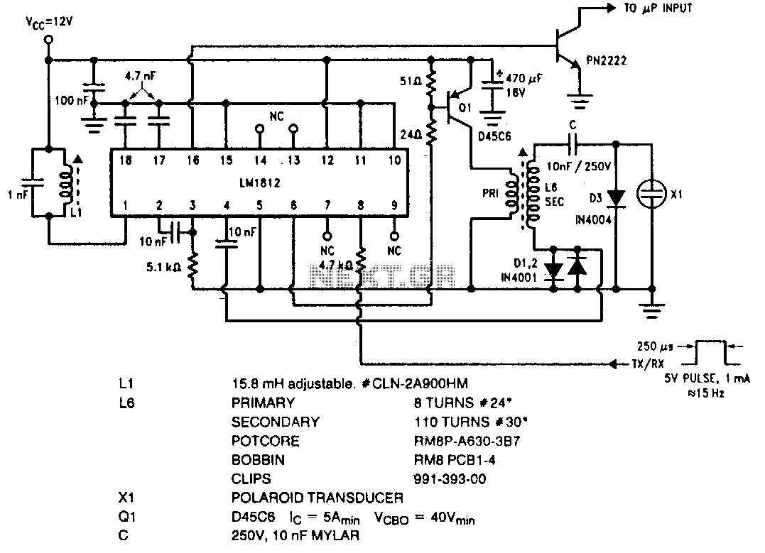
The LM1812 is a complete ultrasonic transceiver integrated circuit designed for various pulse-echo ranging applications. The chip functions by transmitting a burst of oscillations through a transducer, which is then used to listen for a return echo. If an...

The 7MHz CW transceiver is constructed using the MC3362P integrated circuit, originally intended for a 10MHz band transceiver. Due to concerns regarding unexpected neighboring spurious signals, the frequency was altered to 7MHz, leading to the completion of the transceiver....
The transceiver switches the four-element 1500-ohm crystal band-pass filter (BPF) connections between the inputs and outputs of two SA602 integrated circuits to reverse the signal flow for receive/transmit (R/T) operation. Since no intermediate frequency (IF) amplifier is utilized in...
The PMR VHF transceiver Motorola Radius M110 (in further text referred as M110) was manufactured by Motorola GmbH therefore being an European radio. Since many professional radio service users has replaced this transceiver with newer gear, a considerable number...
This design note presents a simple yet feature-rich 16-watt output, universal AC input adapter power supply for modems, hubs, or similar applications. The circuit utilizes a discontinuous mode (DCM) flyback converter topology designed around ON Semiconductor's NCP1027 monolithic current...