
60-120MHz FM Receiver with AFC

AFC is a crucial component in radio frequency (RF) receivers, ensuring that the receiver remains tuned to the desired signal frequency despite variations caused by factors such as drift or interference. The basic block diagram of a receiver typically includes several key components: an antenna, a front-end amplifier, a mixer, a local oscillator (often implemented as a VCO), and a demodulator.
The antenna captures the incoming RF signals, which are then amplified by the front-end amplifier to improve the signal-to-noise ratio. The amplified signal is sent to the mixer, where it is combined with a signal from the local oscillator. The mixer produces an intermediate frequency (IF) signal that is easier to process. The VCO plays a critical role in this process, as it generates a frequency that can be adjusted based on feedback from the AFC circuit.
The AFC circuit continuously monitors the frequency of the incoming RF signal and adjusts the VCO to ensure that it remains locked to the desired frequency. This is typically achieved through a feedback loop that compares the output frequency of the VCO with the incoming signal frequency. If a deviation is detected, the AFC circuit modifies the control voltage applied to the VCO, thereby altering its output frequency to match the incoming signal.
In summary, the integration of AFC in a receiver system enhances its ability to maintain accurate tuning, thereby improving overall reception quality and reducing the impact of frequency drift and interference. The block diagram serves as a foundational reference for understanding the functional relationships between the various components involved in RF signal processing.We can say in simple words that AFC will lock the receiver to any valid RF signal. Below, we can see a basic block diagram of an receiver. The VCO is mixed with. 🔗 External reference
Related Circuits
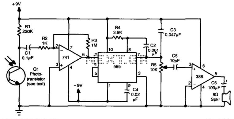
This receiver utilizes an IR-sensitive phototransistor (such as those from Clairex or HP) housed within a light-tight enclosure that features an aperture for the incoming infrared beam. An optical system may be integrated with this receiver to enhance its...
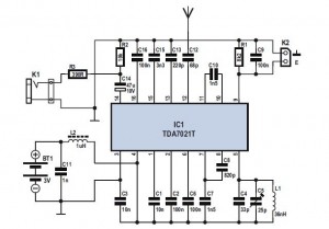
The FM Radio Receiver IC TDA 7012T is a straightforward component that offers excellent sensitivity and selectivity for FM radio reception. This single-chip FM receiver, known as IC TDA7012T, requires minimal additional components to construct an FM receiver. The...
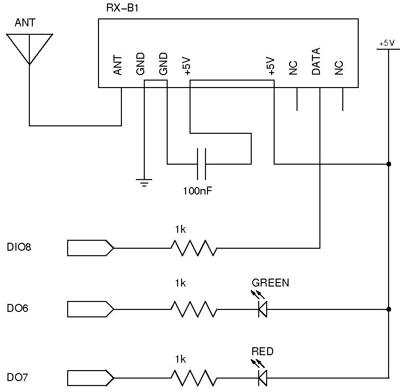
The documentation and code cleaning for the Jaycar Thermor/BIOS branded wireless weather station receiver has been completed. The code is based on the Practical Arduino weather station receiver project. The process involved analyzing the RF signal from the weather...
The performance of this sensitive ultrasonic receiver is impressive. It allows users to listen to various sources of ultrasonic sounds, including bugs, bats, and engines. The circuit utilizes a piezo tweeter as an ultrasonic microphone, with amplifier stages Q1...
Pictured above is a little AM superhetrodyne receiver that covers the broadcast band from 550 Khz to 1650 Khz. The circuit employs the 8 pin Signetics balanced mixer IC (NE602) which converts the incoming RF signal to the standard...
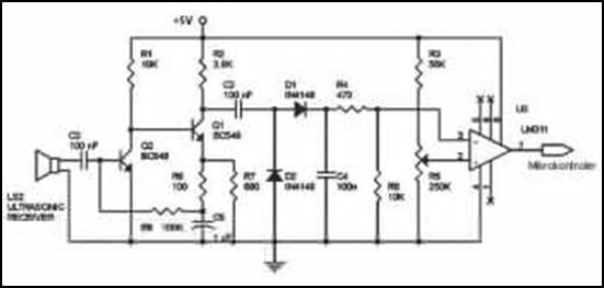
Ultrasonic receivers detect an ultrasonic signal emitted by an ultrasonic transmitter at a specific frequency. The received signal is filtered using a band-pass filter circuit that allows only the predetermined frequency range to pass. The output signal is then...