
AM Radio Receiver schematic

Assemble the NE602, ferrite antenna loopstick, tuning cap, oscillator coil and associated other parts on the breadboard.
Next, connect the battery through a DMM and verify 3 or 4 milliamps of current flow.
Next, adjust the tuning cap for maximum capacitance (550KHz) and connect a scope to pin 6 of the NE602 and verify a approx 1 volt p-p sine waveform. Adjust the red slug of the T1 oscillator coil for a frequency of about 1 MHz. Then adjust the capacitor to minimum capacitance and verify the frequency increases to around 2Mhz.
To adjust the oscillator without a scope, use a portable AM radio to verify the oscillator is working and the frequency is right. To do this, place the portable radio close to the antenna coil and tune it to a AM station around 1000 on the band. Set the circuit tuning dial to the station frequency minus 455KHz. For example, if the portable radio is set to 1100, the circuit tuning dial should point to (1100-455 = 645KHz). This doesn't have to be exact, but set things as close as you can. Next, adjust the red oscillator coil slug until a beat frequency is heard on the portable radio. You should hear a squeal and then a null as the oscillator frequency gets near the station point on the band. This will verify the oscillator is running at about 455 Khz above the dial setting.
If the oscillator doesn't run, the problem may be the connections to the (red) oscillator coil. The red oscillator coil will have 5 connections, 3 on one side for the tapped primary, and 2 on the other for the secondary. The circuit requires only the single, tapped primary side, but unfortunately the primary tap is too close to one end for the circuit to operate. To overcome this problem, the secondary is added in series with the primary which effectively moves the tap closer to the center and provides more feedback to sustain oscillations. The phasing of the secondary connections is also important. If the oscillator fails to work, try reversing the connections to the secondary of the coil. When the oscillator is setup, the remainder of the receiver can be assembled and calibrated.
If you have a signal generator, set it for 600KHz, 30% audio modulation and 1 volt output. Connect the generator through a 1K resistor and a couple turns of wire around the antenna loopstick. Adjust the yellow and black coil slugs and also the position of the antenna coil on the loopstick for strongest response. Reduce the generator output as the signal improves so you can find a peak for all three coils. You can also make small adjustments to the oscillator coil to get the tuning dial to point directly at 600. This will calibrate the low end of the band. To calibrate the high end, set the generator for some frequency near the high end, maybe 1500 on the dial. Tune the receiver so it receives the signal and then adjust the two trimmer capacitors located on the back of the tuning capacitor for best response. You may find at this point the trimmer caps are all the way closed or open and a peak cannot be found. To fix this problem, note which way the caps are set and slightly adjust the main tuning dial to compensate. For example, if the caps are all the way closed, move the tuning dial to a lower setting (more capacitance) and then repeak the trimmers. Continue this until you can find a peak where the trimmers caps are not fully closed or open. At this point, repeat the adjustments at the low and high end until both are optimum.
This same procedure can be done without the generator using a couple local radio stations at opposite ends of the band. The first thing to do is identify a station that can be heard somewhere on the band. Try to do this without adding an external antenna, but if no stations are heard, add a short 2 foot wire antenna to the antenna input at the gate of the JFET. Find the strongest station and slide the antenna coil along the loopstick for best response and also adjust the yellow and black IF coils. Here is a step by step procedure that works reasonably well. The test station was located at 790 on the band.
1. If no stations are heard, connect a short 2 foot wire antenna to the junction of the antenna loopstick and gate of the JFET.
2. Adjust the tuning capacitor and slide the antenna coil for best response of some local station.
3. Adjust the yellow and black slugs of T2 and T3 for loudest response.
4. Reduce the length of the wire antenna and readjust the position of the antenna coil for best response.
5. Move the tuning dial slightly toward the correct point without losing the station. (i.e.) If the station is located at 700 and your tuning dial is pointing higher at 750, slightly move it down toward the correct 700 point (more capacitance).
6. Readjust T2, T3, and antenna coil for best response.
7. Repeat steps 4, 5, and 6 until the station is heard loud and clear and no further improvement can be made.
8. Remove the wire antenna and readjust the antenna coil, T2, and T3 for best response. Note the antenna coil should not end up at the center of the loopstick. This will indicate not enough inductance and a few more turns of wire may be needed on the antenna coil. The optimum position for the coil is near the center, slightly offset toward one end. If it ends up very near one end of the stick, consider removing a few turns which will allow the coil to be closer to the center.
9. At this point, several stations should be heard loud and clear, but minor adjustments may be needed to optimize the entire band. Select a station near the bottom of the band (600KHz) and adjust the antenna coil and oscillator coil for best response. Note that only very small adjustments to the red oscillator coil may be needed. Then select a station near the top of the band (1500KHz) and adjust the two trimmer caps on the back of the main tuning capacitor for best response. Repeat this process until both ends are optimized. Be sure the two trimmer caps do not end up fully open or closed. If they do, note the position and slightly adjust the main capacitor to compensate. For example, if the trimmers are fully closed, adjust the main capacitor slightly lower (more capacitance) and then readjust the trimmers so the peak occurs somewhere between min and max.
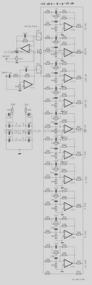
The AM superhetrodyne receiver circuit is a classic design that utilizes a balanced mixer, an intermediate frequency (IF) stage, and an audio amplification stage to achieve effective radio signal reception. The NE602 mixer IC serves as the core component that processes incoming RF signals and shifts them to a lower IF frequency, allowing easier amplification and demodulation. The use of a JFET buffer and a Schottky diode for audio recovery ensures minimal signal distortion and high fidelity. The LM386 audio amplifier is selected for its capability to drive small speakers efficiently, making this circuit suitable for portable applications. The tuning process emphasizes the importance of precise adjustments to the LC circuits, which are crucial for optimal performance across the AM broadcast band. The described calibration procedures illustrate the practical aspects of setting up the receiver, emphasizing the need for iterative tuning and testing to achieve the best reception quality.Pictured above is a little AM superhetrodyne receiver that covers the broadcast band from 550 Khz to 1650 Khz. The circuit employs the 8 pin Signetics balanced mixer IC (NE602) which converts the incoming RF signal to the standard 455 Khz IF signal and provides about 13dB gain.
The IF signal is amplified by a single transistor stage and audio is recovered using a biased shotkey diode (5082) and JFET buffer transistor. The LM386 audio amp is used to drive a small 2.5 inch speaker at about 200 milliwatts. The circuit contains four LC tuned circuits, all of which need to be fine tuned to obtain good results.
An oscilloscope and RF signal generator are useful, but the circuit can also be setup using local radio stations and an additional portable AM radio. For test purposes, the circuit can be assembled on a solderless breadboard so changes can easily be made. Try to use short connections for the RF section with the antenna loop a couple inches away from the board.
Assemble the NE602, ferrite antenna loopstick, tuning cap, oscillator coil and associated other parts on the breadboard. Next, connect the battery through a DMM and verify 3 or 4 milliamps of current flow. Next, adjust the tuning cap for maximum capacitance (550KHz) and connect a scope to pin 6 of the NE602 and verify a approx 1 volt p-p sine waveform.
Adjust the red slug of the T1 oscillator coil for a frequency of about 1 MHz. Then adjust the capacitor to minimum capacitance and verify the frequency increases to around 2Mhz. To adjust the oscillator without a scope, use a portable AM radio to verify the oscillator is working and the frequency is right. To do this, place the portable radio close to the antenna coil and tune it to a AM station around 1000 on the band.
Set the circuit tuning dial to the station frequency minus 455KHz. For example, if the portable radio is set to 1100, the circuit tuning dial should point to (1100-455 = 645KHz). This doesn't have to be exact, but set things as close as you can. Next, adjust the red oscillator coil slug until a beat frequency is heard on the portable radio. You should hear a squeal and then a null as the oscillator frequency gets near the station point on the band.
This will verify the oscillator is running at about 455 Khz above the dial setting. If the oscillator doesn't run, the problem may be the connections to the (red) oscillator coil. The red oscillator coil will have 5 connections, 3 on one side for the tapped primary, and 2 on the other for the secondary. The circuit requires only the single, tapped primary side, but unfortunately the primary tap is too close to one end for the circuit to operate.
To overcome this problem, the secondary is added in series with the primary which effectively moves the tap closer to the center and provides more feedback to sustain oscillations. The phasing of the secondary connections is also important. If the oscillator fails to work, try reversing the connections to the secondary of the coil. When the oscillator is setup, the remainder of the receiver can be assembled and calibrated. If you have a signal generator, set it for 600KHz, 30% audio modulation and 1 volt output. Connect the generator through a 1K resistor and a couple turns of wire around the antenna loopstick.
Adjust the yellow and black coil slugs and also the position of the antenna coil on the loopstick for strongest response. Reduce the generator output as the signal improves so you can find a peak for all three coils. You can also make small adjustments to the oscillator coil to get the tuning dial to point directly at 600.
This will calibrate the low end of the band. To calibrate the high end, set the generator for some frequency near the high end, maybe 1500 on the dial. Tune the receiver so it receives the signal and then adjust the two trimmer capacitors located on the back of the tuning capacitor for best response.
You may find at this point the trimmer caps are all the way closed or open and a peak cannot be found. To fix this problem, note which way the caps are set and slightly adjust the main tuning dial to compensate.
For example, if the caps are all the way closed, move the tuning dial to a lower setting (more capacitance) and then repeak the trimmers. Continue this until you can find a peak where the trimmers caps are not fully closed or open. At this point, repeat the adjustments at the low and high end until both are optimum. This same procedure can be done without the generator using a couple local radio stations at opposite ends of the band.
The first thing to do is identify a station that can be heard somewhere on the band. Try to do this without adding an external antenna, but if no stations are heard, add a short 2 foot wire antenna to the antenna input at the gate of the JFET. Find the strongest station and slide the antenna coil along the loopstick for best response and also adjust the yellow and black IF coils.
Here is a step by step procudure I found works reasonably well. My test station was located at 790 on the band. 1. If no stations are heard, connect a short 2 foot wire antenna to the junction of the antenna loopstick and gate of the JFET. 2. Adjust the tuning capacitor and slide the antenna coil for best response of some local station. 3. Adjust the yellow and black slugs of T2 and T3 for loudest response. 4. Reduce the length of the wire antenna and readjust the position of the antenna coil for best response.
5. Move the tuning dial slightly toward the correct point without losing the station. (i.e.) If the station is located at 700 and your tuning dial is pointing higher at 750, slightly move it down toward the correct 700 point (more capacitance). 6. Readjust T2,T3 and antenna coil for best response. 7. Repeat steps 4, 5 and 6 until the station is heard loud and clear and no further improvement can be made.
8. Remove the wire antenna and readjust the antenna coil, T2 and T3 for best response. Note the antenna coil should not end up at the center of the loopstick. This will indicate not enough inductance and a few more turns of wire may be needed on the antenna coil. The optimum position for the coil is near the center, slightly offset toward one end. If it ends up very near one end of the stick, you may want to remove a few turns which will allow the coil to be closer to the center.
9. At this point, several stations should be heard loud and clear but minor adjustments may be needed to optimize the entire band. Select a station near the bottom of the band (600KHz) and adjust the antenna coil and oscillator coil for best response.
Note that only very small adjustments to the red oscillator coil may be needed. Then select a station near the top of the band (1500Khz) and adjust the 2 trimmer caps on the back of the main tuning capacitor for best response. Repeat this process until both ends are optimized. Be sure the 2 trimmer caps do not end up fully open or closed. If they do, note the position and slightly adjust the main capacitor to compensate. For example, if the trimmers are fully closed, adjust the main capacitor slightly lower (more capacitance) and then readjust the trimmers so the peak occurs somewhere between min and max.
🔗 External reference
Related Circuits

This circuit generates sine and square wave signals with frequencies ranging from below 20 Hz to above 20 kHz. The advantage of this circuit diagram is that the output frequency can be adjusted by varying the variable resistor R6. The...
The most commonly available headphones have an impedance of 2 × 32 Ω. This relatively low value makes them unsuitable for certain designs. However, with some clever modifications, these headphones can be adapted for such applications. To achieve this,...
The diagram illustrates a circuit comprising 10 identical units, each varying only in the capacitance values of their capacitors, which determine the frequency band for each filter. Potentiometers are utilized to adjust the designated frequency regions in each unit....
The TDA7088T can be used in mono portable and pocket radios. This is a bipolar integrated circuit. Here is one of the application circuit diagrams. The TDA7088T is a versatile bipolar integrated circuit designed specifically for mono FM radio applications,...
The car power amplifier utilizes the SI1050GL integrated circuit (IC) as the primary amplification component. It delivers an output power of 50 Watts at an 8-ohm mono impedance. The amplifier operates with a DC voltage of up to 25...
This is an anti-theft alarm with wireless connectivity, referred to as the Anti-Theft Car Wireless Alarm. The FM radio-controlled anti-theft alarm can be utilized with any vehicle that operates on a 6 to 12-volt DC supply system. The mini...