
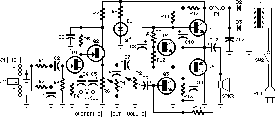
60 Watt Audio Power Amplifier

The circuit design incorporates a series configuration of three diodes, which is critical for establishing a baseline voltage drop necessary for the operation of the subsequent components. The replacement of two diodes with a red LED serves a dual purpose: it not only maintains the desired voltage drop but also provides visual feedback regarding the circuit's operational status. The LED's forward voltage characteristics contribute to improved stability of the quiescent current, particularly beneficial in environments with fluctuating temperatures.
The use of capacitors C1 and C2 is pivotal in filtering and stabilizing the power supply voltage. The minimum values specified ensure that the mono amplifier functions adequately under standard conditions. However, in stereo applications, where load demands are higher, an increase to 10,000 µF is recommended. This larger capacitance value aids in smoothing the power supply output, thus enhancing the overall performance and reducing the likelihood of power supply-induced distortions.
Grounding is a critical aspect of circuit design, particularly in audio applications where noise can significantly impact sound quality. The recommended grounding strategy involves connecting all relevant components—R1, R3, C2, C3, C4, and the ground input wire—to a single ground point. This approach minimizes the potential for ground loops, which can introduce hum and other unwanted noise into the audio signal. Furthermore, the separation of input and output grounds from the power supply ground is essential to maintain signal integrity and prevent interference between different circuit sections.
In summary, the modifications and grounding practices outlined in this circuit description are designed to enhance the performance and reliability of the audio amplifier, ensuring optimal operation across varying conditions while minimizing noise and distortion.In the original circuit, a three-diode string was wired in series to R10. Two of these diodes are now replaced by a red LED in order to achieve improved quiescent current stability over a larger temperature range. Thanks to David Edwards of LedeAudio for this suggestion. The value suggested for C1 and C2 in the Power Supply Parts List is the minimum required for a mono amplifier.
For optimum performance and in stereo configurations, this value should be increased: 10000 µF is a good compromise. A correct grounding is very important to eliminate hum and ground loops. Connect to the same point the ground sides of R1, R3, C2, C3 and C4 and the ground input wire. Connect R7 and C7 to C11 to output ground. Then connect separately the input and output grounds to the power supply ground. 🔗 External reference
Related Circuits
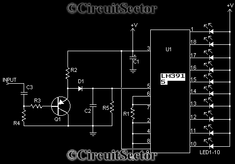
This device can also be referred to as an economical hearing aid, as it can be constructed using low-cost components. Although its performance does not match that of advanced commercially available hearing aids, it can effectively assist individuals with...
The longer the locks remain unused with either the remote or central locking button, the stronger the power surge to the door lock motors. After being activated even once, it seems to drain all the power from the capacitor...

A simple lab power supply electronic project can be designed using this circuit diagram, which is based on the LM2576 monolithic integrated regulator that provides all the active functions for a step-down (buck) switching regulator. As seen in the...
In all instances where Darlington transistors serve as output devices, it is crucial for the sensing transistor (Q4) to maintain close thermal contact with the output transistors. Consequently, a TO126-case transistor type was selected for ease of mounting onto...
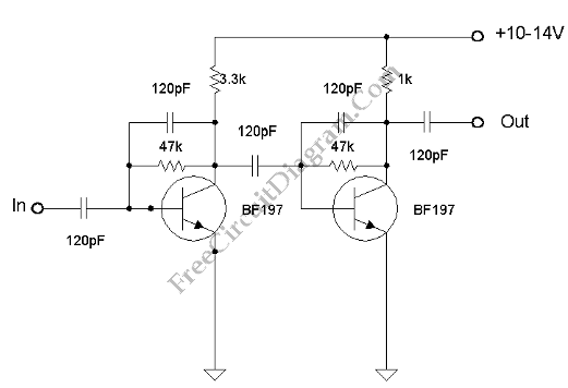
This amplifier has VHF (very high frequency) and UHF (ultra high frequency) response, and it can be used as a receiver booster, for example. Here is the schematic. The described amplifier is designed to enhance signal reception in the VHF...
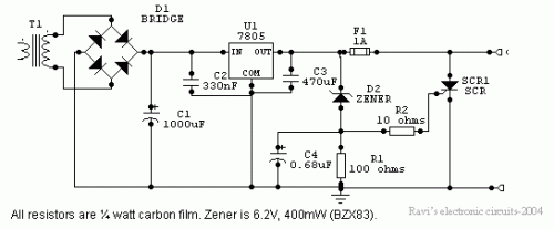
Power supplies designed for use with TTL logic circuitry must protect against over-voltage, which can rapidly damage TTL chips. The duration of over-voltage that can harm TTL chips is too short to activate any conventional fuse, necessitating the use...