
600W rf power amplifier

The described push-pull parallel circuit configuration is designed to operate with four MRF150 RF power FETs, which are known for their high efficiency and capability to handle substantial power levels. By paralleling these FETs, the circuit can effectively distribute the load, thereby enhancing the overall output power while minimizing the thermal stress on individual devices.
The supply voltage range of 40 to 50 Vdc allows for flexibility in operation, enabling the designer to select an appropriate voltage based on the specific linearity requirements of the application. This voltage range is critical in ensuring that the FETs operate within their optimal performance envelope, thus achieving desired amplification characteristics without distortion.
A notable feature of this circuit design is the independently adjustable bias for each FET. This adjustability allows for fine-tuning of the operating point of each transistor, facilitating optimal performance across various operating conditions. The ability to set the bias independently negates the necessity for matching the gate threshold voltages among the FETs, simplifying the design process. This characteristic is particularly advantageous in applications where variations in device characteristics might otherwise lead to performance inconsistencies.
In summary, this push-pull parallel circuit configuration, leveraging the capabilities of the MRF150 RF power FETs, presents a robust solution for high-power RF applications, with adjustable biasing that enhances performance and simplifies circuit design.A unique push-pull parallel circuit. It uses four MRF150 RF power FETs paralleled at relatively high power levels. Supply voltages of 40 to 50 Vdc can be used, depending on linearity requirements The bias for each device is independently adjustable; therefore, no matching is required for the gate threshold voltages.
Related Circuits
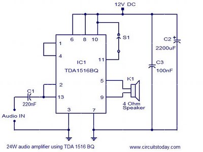
This document presents the circuit diagram of a simple 24W mono amplifier utilizing the TDA1516 integrated circuit. The TDA1516 is a Class B power amplifier housed in a 13-pin SIL package. It incorporates several beneficial features, including short circuit...
This amplifier is designed for outdoor installation and is connected to an indoor power line box. It utilizes either 50-ohm or 75-ohm coaxial cables for the connection between indoor and outdoor units. The amplifier circuit board is depicted in...
In recent years, following the introduction of CDs, vinyl recordings have nearly disappeared. Nevertheless, a phono preamplifier remains useful for listening to old vinyl discs from a well-preserved collection. This simple yet efficient circuit designed for inexpensive moving-magnet cartridges...
The following circuit illustrates a VHF pre-amplifier circuit diagram. This circuit utilizes the BFS17 transistor. Features: designed for VHF applications. The VHF pre-amplifier circuit is essential for enhancing weak radio frequency signals in the VHF (Very High Frequency) range, typically...
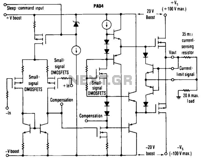
This circuit from Apex Microtechnology can deliver 180 V peak-to-peak at 90 kHz into a 4-ohm load. The PA04 can deliver 400 watts RMS into an 8-ohm load with low total harmonic distortion at frequencies exceeding 20 kHz. The circuit...
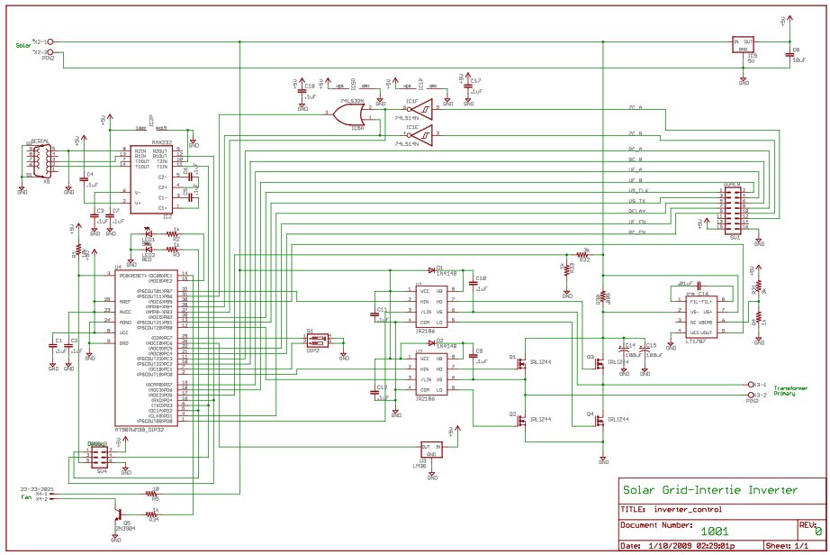
For the last year, a prototype for a solar inverter that can be grid-intertied has been developed. A solar inverter converts 12V DC (or other voltages) from solar panels. The solar inverter is a crucial component in photovoltaic systems, responsible...