
VHF Pre-Amplifier Circuits Diagram Using The BFS17 Transistor

The VHF pre-amplifier circuit is essential for enhancing weak radio frequency signals in the VHF (Very High Frequency) range, typically between 30 MHz and 300 MHz. The BFS17 transistor, a high-frequency NPN transistor, is well-suited for this application due to its low noise figure and high gain characteristics.
In the schematic, the BFS17 is configured in a common-emitter arrangement, which provides significant voltage gain. The input signal is coupled to the base of the transistor through a coupling capacitor, which blocks any DC component while allowing the AC VHF signal to pass through. A biasing network, typically composed of resistors, is employed to set the operating point of the transistor, ensuring it remains in the active region for optimal amplification.
The collector of the BFS17 is connected to a power supply, usually in the range of 5 to 12 volts, allowing it to function efficiently. The output signal is taken from the collector through another coupling capacitor, which again blocks the DC component, allowing only the amplified AC signal to proceed to the next stage of the circuit or to an antenna.
Additional components may include bypass capacitors to stabilize the power supply and improve frequency response, as well as inductors for tuning purposes, which can help to optimize the circuit's performance at specific frequencies. Overall, this VHF pre-amplifier circuit is a critical component in radio receivers, ensuring clear and strong signal reception by amplifying weak incoming signals before they are processed by subsequent stages.The following circuit shows about VHF Pre-Amplifier Circuits Diagram. This circuit using the BFS17 Transistor. Features: used as a VHF .. 🔗 External reference
Related Circuits
The IR photo transistor Q1 (Radio Shack 276-145A) or a similar component is connected to the set input (pin 6). It is essential to shield the photo transistor from direct light to ensure that the voltage at the set...
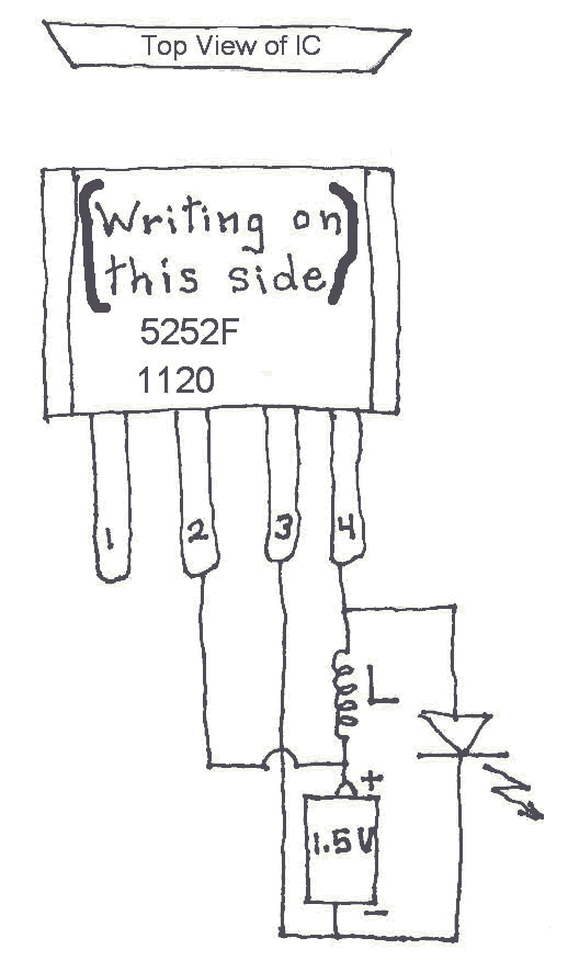
Many Joule Thief circuits traditionally rely on a bulky toroidal inductor that requires careful winding with copper wire. However, there are now compact 4-legged integrated circuits (ICs) available that can perform the same function using only a simple inductor,...
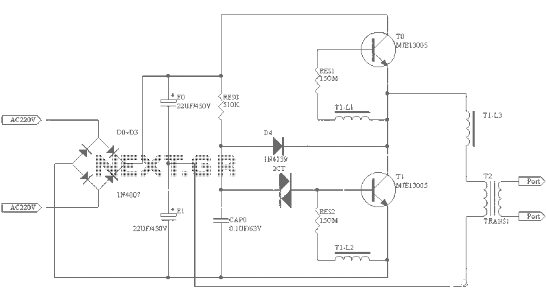
A small (2 to 3 meters) neon electronic transformer circuit diagram is provided below. The described circuit diagram is intended for use with neon lighting systems, specifically those requiring a transformer to operate efficiently within a range of 2 to...
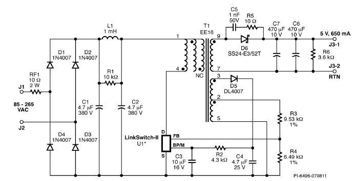
A simple 3.25W constant voltage/constant current (CV/CC) charger can be designed using the LinKSwitch family IC manufactured by Power Integrations. This electronic circuit project is intended to provide a 5-volt output with a maximum current of 650mA. The 3.25W...
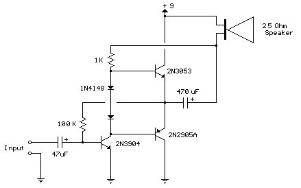
Improved 3 Transistor Audio Amplifier. The load resistor for the driver transistor is connected directly to the positive supply. This configuration has a disadvantage in that as the output moves positive, the voltage drop across... The improved three-transistor audio amplifier...
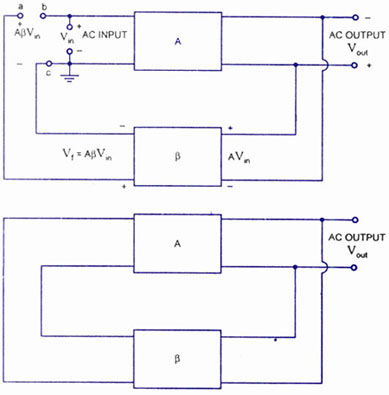
A feedback amplifier with a closed-loop gain, Af, greater than unity can be achieved through the use of positive feedback. This condition also fulfills the phase requirement, leading to the operation of an oscillator circuit. An oscillator circuit generates...