
60W FM Linear amplifier

The 60 Watt linear amplifier circuit utilizes the IRF840 power MOSFET, a robust component known for its high power handling capabilities, making it suitable for applications requiring significant output power. The design operates efficiently at a supply voltage (Vcc) of 60 volts and draws a current of approximately 700 mA, resulting in a total power consumption of around 42 watts, with a maximum output of 60 watts achievable when properly configured.
The circuit requires careful thermal management; therefore, a heat sink is essential to dissipate heat generated during operation. The amplifier can be tested using a dummy load, which can be a 24V 6W bulb or a 230V 60W bulb, depending on the voltage level used in the circuit. The use of a dummy load is crucial for safe operation during alignment and testing phases, ensuring that the amplifier does not output to an open circuit, which could lead to damage.
The gate voltage is a critical parameter for the IRF840; it is recommended to maintain it at a safe level, ideally around 1V, to prevent self-oscillation that could potentially destroy the transistor. The circuit includes a 10K preset resistor for adjusting the drain current to approximately 100 mA, which is essential for optimal performance.
The transformer used in the amplifier, designated as T1, is constructed as a bifilar winding with 8 turns of 26 SWG wire on a 1.4 x 1 balun core. This configuration supports efficient signal transfer and helps in maintaining the desired frequency response. Additionally, a coil wound on the drain of the IRF840 consists of 3 turns of 20 SWG wire on a pair of T13.9 toroids, which are stacked to form a balun core, aiding in impedance matching and reducing signal loss.
The radio frequency choke (RFC) in the Vcc line is designed with 20 turns of 20 SWG wire on a T20 toroid, which helps in filtering out unwanted high-frequency signals and stabilizing the power supply to the amplifier. This arrangement ensures that the amplifier operates within safe limits, providing a reliable and efficient amplification of the input signal.The 60 Watt linear amplifier is simple all solid state circuit using power mosfet IRF840. The IRF series of power transistors are available in various voltage and power ratings. A single IRF840 can handle maximum power output of 125 watts. Since these transistors are used in inverters and smps they are easily available for around Rs: 20/-. The IRF linear amplifier can be connected to the out put of popular VWN-QRP to get an output of 60 Watts.
The circuit draws 700 ma at 60 Volt Vcc. Good heat sink is a must for the power transistor. Alignment of the circuit is very easy. Connect a dummy load to the out put of the circuit. You can use some small bulb like 24V 6Watts as the dummy load. I have even used 230V 60Watts bulb as dummy load with my IRF840 power amplifier working at 120Volts. Adjust the 10K preset to get around 100 ma Drain current. I used gate voltage of 0.8V with my linear amplifier. A heigh gate voltage can make the power transistor get distroyed by self oscillation. So gate voltage must be below 2V and fixing at 1V will be safe. Bifalar transformaer T1 is wound with 8 turns 26SWG on 1.4 x 1 balun core. The coil on the drain of IRF is 3 turns 20 SWG wound on 4 number of T13.9 torroids (two torroids are stacked to form a balun core). The RFC at the Vcc line is 20 Turns 20 SWG wound on T20 torroid. 🔗 External reference
Related Circuits
This is a universal 1 Watt RF class C amplifier that is ideally suited for low power FM transmitters. The input should be at least 100mW to achieve a 1W output. It is recommended to enclose the amplifier in...
A common collector amplifier circuit structure and its key components are outlined. The composition of the common collector amplifier circuit is fundamentally similar to that of a common emitter amplifier circuit, with two notable exceptions: one is the collector...
Here is the schematic for an 8 watt audio amp. This amp can be used as a simple booster, the heart of a more complicated amplifier or used as a guitar amp. The circuit can be built on a...
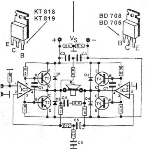
This audio amplifier circuit provides up to 200 W of high-quality output for loudspeakers with impedances ranging from 4 to 16 ohms. The operating voltage is between 24 and 36 V, with a maximum current of 5 A. The audio...
This amp delivers a lot of power and uses 1 IC and two power transistors. The circuit consists of an amplifier IC (a TDA 2030A) and a power stage consists of two transistors. The amplifier can be powered with...
The basis for this amplifier has been around now for several years as Project 3A, and requires only relatively small modifications to be able to operate in Class-A. The biggest change is in output power (reduced dramatically from the 60-100W...