
A common collector amplifier

The common collector amplifier, also known as an emitter follower, is a three-terminal electronic circuit configuration that provides high input impedance and low output impedance. The circuit typically consists of a single NPN or PNP transistor, with the emitter terminal serving as the output. The input signal is applied to the base terminal, while the output is taken from the emitter terminal, making the circuit an effective buffer.
In this configuration, the biasing of the transistor is crucial for maintaining proper operation. The two bias resistors connected to the base are typically chosen to ensure that the transistor operates in the active region, allowing for linear amplification of the input signal. The values of these resistors can be calculated based on the desired quiescent current and the transistor's characteristics.
The load resistor connected to the emitter is responsible for setting the gain of the amplifier. The gain of a common collector amplifier is approximately equal to one, meaning that the output voltage closely follows the input voltage but with a lower output impedance. This characteristic is particularly useful in applications where impedance matching is necessary, such as driving low-impedance loads or interfacing with other circuit stages.
The capacitors in the circuit perform vital roles in AC coupling. They block any DC component of the input signal while allowing the AC component to pass through. This ensures that only the desired AC signal is amplified, preventing any DC offset from affecting the operation of subsequent stages in the circuit.
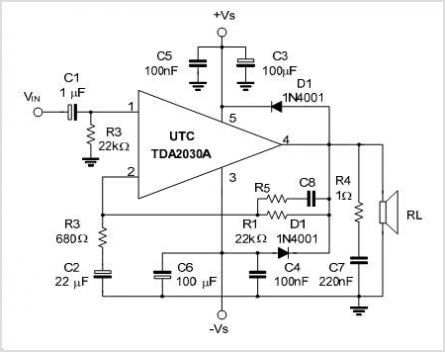
In summary, the common collector amplifier is a versatile and widely used configuration in electronic circuits, offering benefits such as impedance matching, buffering capabilities, and signal integrity. Proper selection of components and biasing techniques is essential for optimal performance in various applications, including audio amplifiers, signal conditioning, and interfacing circuits.A common collector amplifier (1) common collector amplifying circuit structure and key components of common collector amplifier circuit as shown, the key components of the comp osition and common emitter amplifier circuit is basically the same, except there are two: One is the collector resistors Mu to the emitter (indicated by Van), and the second is the output signal from the collector but no longer taken from the emitter. In this circuit, two adjacent bias resistor R l and it is through the power supply to the base of the transistor (b) power supply: Rc is the transistor emitter (e) of the load resistor; two capacitors are played through exchange compartment DC coupling capacitor effect: the resistor Rr is a minus plant output signal load resistor.
Common-emitter transistor amps, NPN and PNP type transistor amplifier Sheng also big differences between different power supply. Since the transistor amplifier circuit of the power supply resistance is very small, the AC signal is equivalent to a short circuit between positive and negative.
Equivalent AC power supply, i.e. the collector of the transistor (c) corresponds to the ground. The input signal is loaded into the base of the transistor (b) and polar (e) and the emission load resistor between Burgundy, loaded into the base of the transistor (b) and collector (c) it is equivalent to between the output signal from the transistor emitter electrode (e), it is equivalent to between transistors from the pole (e) and collector (c) emission and therefore the collector (c) for the input signal and the output signal common terminal number, it is called common collector electrode amplifier.
Related Circuits
The TDA2549 is a complete intermediate frequency (IF) circuit that includes automatic frequency control (AFC), automatic gain control (AGC), demodulation, and video preamplification capabilities for multistandard television receivers. It can process both positively and negatively modulated video signals in...
Many times we needed to use a simple circuit of preamplifier, with few components and facility of made. This circuit uses an opamp, the Motorola, TCA5550, that contains a double amplifier, as outputs for the adjust of volume, balance,...
A buffer amplifier is necessary for a typical pH probe to isolate its source resistance, which ranges from 10^6 to 10^9 ohms, from the external circuitry. Such an amplifier is illustrated in the... The buffer amplifier serves a critical role...
The LM383 schematic represents an 8-watt audio amplifier, which is straightforward to construct as a mini-audio power amplifier. The parts list includes the following components: C1 - 1 unit of a 10µF electrolytic capacitor, C2 - 1 unit of...
This schematic diagram illustrates a 70W power amplifier utilizing MOSFET technology for audio systems. Alternative input stage transistors include the Toshiba 2SA970BL and 2SC2240BL, which serve as suitable substitutes for the Hitachi 2SA1085E. The 70W power amplifier is designed to...
The circuit features a Class AB audio amplifier integrated circuit (IC) that necessitates only a minimal number of external components. This series is straightforward to construct. The 10W stereo amplifier circuit requires a stable power supply with a voltage...