
6418 Tube RIAA Phono Preamplifier

The Oatley Electronics K282 tube-based stereo RIAA preamplifier kit is designed to provide a high-quality audio experience for moving magnet cartridges, making it an excellent choice for enthusiasts seeking an affordable entry into tube amplification. The use of JAN 6418 pentode valves ensures a warm, rich sound characteristic of tube amplifiers, while the dual-stage design enhances signal integrity and fidelity. The incorporation of FET buffering allows for improved linearity and reduced distortion, further enhancing audio performance.
The power supply configuration is noteworthy, utilizing the MC34063A IC to achieve a higher voltage from a low-voltage source, which is essential for powering the tube stages effectively. The choice of a switch-mode power supply not only minimizes the footprint but also increases efficiency, reducing heat generation during operation.
The PCB layout, with its double-sided design and extensive grounding, is optimized for minimal interference and noise, which is particularly critical in audio applications. The option to upgrade passive components provides flexibility for users who may wish to tailor the sound characteristics to their preferences, allowing for a customized listening experience.
Assembly instructions are provided in detail, ensuring that builders can confidently construct the preamp with basic soldering skills. The inclusion of rubber grommets to mitigate microphonics demonstrates attention to detail, addressing a common issue in tube amplifiers. The use of gold-plated RCA connectors ensures reliable signal transmission and longevity.
Overall, the Oatley Electronics K282 kit represents a well-thought-out approach to introducing users to tube-based audio amplification, combining ease of assembly with the potential for high-quality sound reproduction.Last year I built and reviewed the low cost Oatley Electronics K272 Tube Stereo Headphone Amplifier Kit. In conversation with Oatley Electronics (located in New South Wales Australia), they told me that the kit became very popular and sold pretty much all over the world.
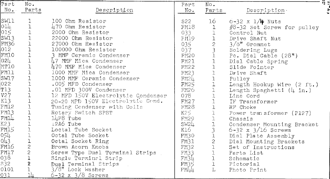
The little headphone amplifier kit was based around new old stock Raytheon J AN 6418 sub-miniature pentode valves (tubes). Using the same JAN 6418 valves Oatley Electronics has released an inexpensive ($47AU, May 2010) tube based stereo RIAA preamplifier kit for moving magnet (MM) cartridges, and they were kind enough to send me a couple of kits. The printed circuit board (PCB) is double sided, solder masked and silk screened. Almost the entire top layer of the PCB is grounded to provide shielding. To keep the kit price low, the passive components are very basic. A mix of metal film and carbon resistors, polyester, ceramic and electrolytic caps. Polyester caps are generally not used in audio circuits because some say they do not sound good. Of course one can choose to upgrade the passive parts. The contents of the phono RIAA preamp kit are shown below. A full parts list of the kit contents is included in the Oatley Electronics K282 Kit Instructions (PDF - 646kB).
The external power supply is a small 5V switch-mode power supply (SMPS) with a universal outlet adapter that can be used with American, European, Australasian and UK power outlets (100 - 240VAC). The circuit uses a MC34063A switched mode power supply integrated circuit (IC) to convert the 5V external supply to 30V.
The switching frequency is set at around 100kHz. The phono preamp circuit is a two stage affair with each valve stage buffered by a 2SK170 Field Effect Transistor (FET). The new old stock (NOS) JAN 6418 tubes are used in pentode mode. The schematic of the tube phono preamp kit is shown in Figure 1. Please note that this circuit is © Oatley Electronics and permission to host the schematic on this site has been provided by Oatley Electronics.
A high resolution image of the schematic is available in the kit instructions. The kit is fairly complete, however the builder will need to supply input and output connectors (typically RCA) and most will likely want to build the kit into some sort of enclosure. A completed kit using only the supplied parts is shown below. Following the instructions supplied with the kit, assembly is very straight forward, but you will require basic soldering skills.
The inductor will need to be wound (14 turns) and full details for constructing the inductor are included in the instructions. The JAN 6418 valves are very microphonic. Two tight fitting rubber grommets (supplied with the kit) on each valve will help reduce microphonics significantly.
Place the grommets on the tubes prior to soldering them to the PCB. There are no special tools that are required, but you will need the basics, such as a soldering iron, wire cutters and wire strippers. For my frist phono kit build, I used single strand fine copper wire (~26Ga) for the signal wiring. Usually with sensitive and high gain circuits one would use shielded wire as hook-up wire. If you used unshielded wire like I did, tightly twist the signal and signal ground wires (I used an electric drill) to keep unwanted noise out of the wiring.
For the internal power connections I used multi-strand wire (~22Ga) which I twisted together. The on / off control is a single-pole, single-throw (SPST) swtich connected to the 5V supply with a faint blue LED to indicated power. The input and output connections are gold plated RCA jacks. I decided to enclose the phono preamp kit into a medium size cast aluminum case. I always paint these cases and this time would be no exception. Usually I paint in a gloss black or red. The paint I use is epoxy enamel and though it takes a week to dry hard it forms a very tough coat. Prior to painting I thoroughly sand the exterior of the cas 🔗 External reference
Related Circuits
The circuit is based on a single operational amplifier integrated circuit designed to produce a modular preamplifier that operates in Class A configuration. The modular preamplifier circuit utilizes a single operational amplifier (op-amp) integrated circuit, which serves as the primary...
This circuit is mainly intended to provide common home stereo amplifiers with a microphone input. Using a stereo microphone the circuit must be doubled. In this case, two separate level controls are better than a dual-ganged stereo potentiometer. Low...
Construct this circuit using any preferred method, ensuring that high voltage safety measures are strictly adhered to. Proper insulation is crucial, and bare conductors must be spaced at least 2mm apart to avoid arcing. This circuit functions as a...
This circuit is an FM 88-108 MHz receiver. The FM receiver circuit operates within the frequency range of 88 to 108 MHz, which is the standard FM broadcasting band. The core components of an FM receiver typically include an antenna,...
The Audio Research Corporation LS22 Line Stage Preamplifier was selected for this upgrade. The Audio Research LS22 Line Stage Preamplifier is a high-performance audio component designed to enhance the quality of sound reproduction in audio systems. This preamplifier features a...
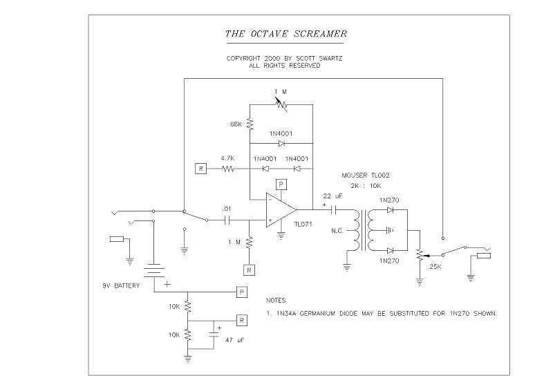
I recently prototyped a Tube Screamer type circuit to refresh my memory about the sound of this pedal. I used a borrowed TS-808 and a Pro Reverb in the mid 80s for several weeks while my modded Twin Reverb...