
Class A Modular Preamplifier with Single Integrated Circuit

The modular preamplifier circuit utilizes a single operational amplifier (op-amp) integrated circuit, which serves as the primary amplification element. In a Class A configuration, the op-amp operates with a continuous current flow through the output stage, ensuring that the amplifier is always active and providing linear amplification of the input signal. This configuration is known for its high fidelity and low distortion characteristics, making it suitable for audio applications and other scenarios where signal integrity is paramount.
The circuit typically includes passive components such as resistors and capacitors to set the gain, filter unwanted frequencies, and stabilize the operation of the op-amp. Input and output coupling capacitors may be employed to block DC offsets while allowing the AC signal to pass through. The gain of the amplifier can be adjusted by changing the feedback resistor values, allowing for flexibility in the design based on the specific application requirements.
Power supply considerations are also crucial in the design of this preamplifier. A dual power supply configuration (positive and negative voltages) is often used to maximize the output swing and minimize distortion. Proper decoupling capacitors should be placed near the power supply pins of the op-amp to ensure stable operation and reduce noise.
Overall, this modular preamplifier circuit is a versatile solution for enhancing weak audio signals, providing a clean and amplified output suitable for further processing or direct driving of loads.The circuit was based on a single operational amplifier integrated circuit that is made to produce a modular preamplifier which functions in the Class A o.. 🔗 External reference
Related Circuits
The VFC62 is a voltage-to-frequency and frequency-to-voltage converter that effectively transforms analog signals into digital signals. The digital output is presented in an open collector format, where the digital pulse repetition rate is directly proportional to the amplitude of...
This circuit is designed to indicate when a plant requires watering. An LED blinks at a low frequency when the soil in the flower pot is excessively dry, turning off as the moisture level rises. The sensitivity of the...
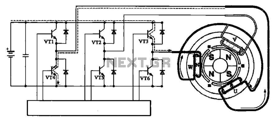
The brushless motor consists of a rotor, a stator, and a drive circuit. The relationship between the brushless motor rotor, stator, and drive circuit is illustrated in the accompanying figure. In the initial state, VT3 and VT4 are conducting,...
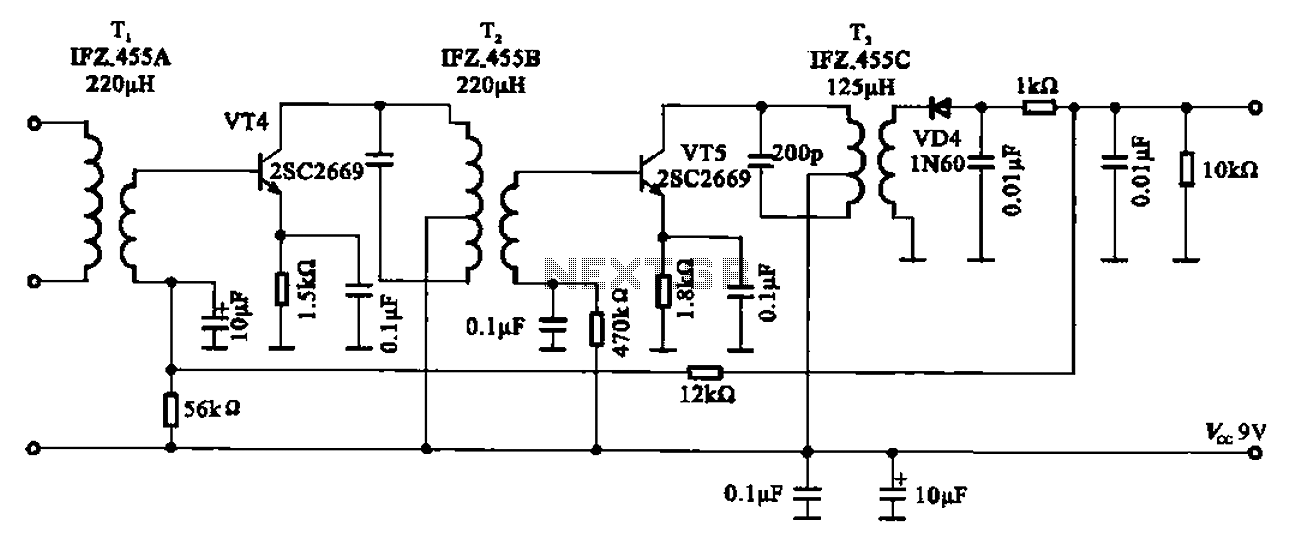
AM radio shows the IF amplifier and detector circuit. The mixer receives the intermediate frequency output signal from the transformer after the device. This signal is applied to the base of the intermediate frequency transistor VT4. The collector load...
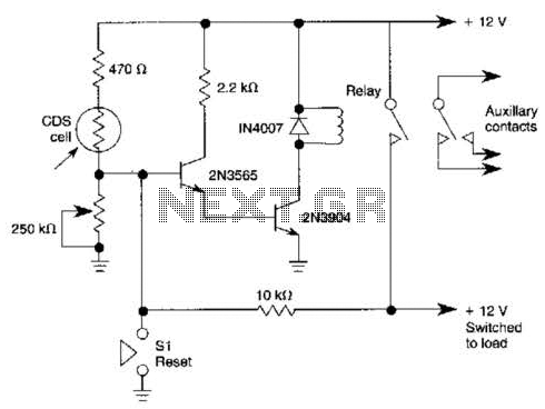
When light strikes the CDS cell, it activates the transistors, which in turn energizes the relay, causing it to latch. Pressing switch SI grounds the base of the 2N3565 transistor, thereby resetting the relay. Additionally, a 250 k potentiometer...
At low output power, up to 18 W, the device functions as a standard BTL amplifier. When a greater output voltage swing is necessary, the internal supply voltage is increased using external electrolytic capacitors. This momentarily elevated supply voltage...