
6v 4.5ah battery charger circuit

The circuit utilizes the LM317T voltage regulator, which is a versatile component capable of providing a stable output voltage, making it suitable for battery charging applications. The LM317T is configured in such a way that it regulates the voltage to the appropriate level required for charging a 6V lead-acid battery, ensuring that the battery receives the correct charging voltage without overcharging.
The design typically includes a few passive components such as resistors and capacitors. Resistors are used to set the output voltage of the LM317T, while capacitors are employed to stabilize the voltage and filter out any noise from the power supply. Additionally, a diode may be included in the circuit to prevent reverse current flow, which could damage the charger or the battery.
The automatic feature of the charger is achieved through the use of a simple feedback mechanism that monitors the battery voltage. When the battery reaches its full charge, the circuit can automatically reduce or cut off the charging current, thus preventing overcharging and extending the life of the battery.
This circuit is particularly useful for applications where a reliable and efficient charging solution is required for 6V lead-acid batteries, such as in small electric vehicles, backup power systems, and various portable devices. The simplicity of the design allows for easy assembly and troubleshooting, making it an ideal project for both beginners and experienced electronics enthusiasts.Article about full automatic 6V 4.5AH battery charger circuit with schematic using IC LM317T and few components. The circuit can charge 6V lead acid battery. .. 🔗 External reference
Related Circuits
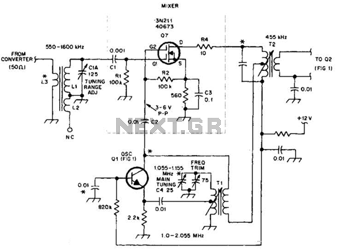
This circuit is an enhanced front end for upgrading a transistor AM receiver. This front end is beneficial when the radio is intended to function as a tunable IF amplifier with shortwave converters. The circuit described serves as a sophisticated...
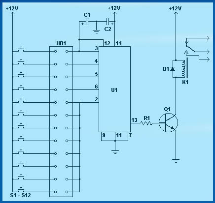
Circuit diagram schematics of electronic keys, electronic locks, digital electronic locks, transistor code locks, and combination electronic locks. The circuit schematics for electronic locking mechanisms encompass a variety of designs tailored to enhance security and convenience in access control systems....
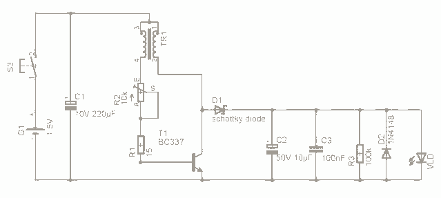
For the past few days, research has been conducted on an intriguing boost circuit known as the Joule Thief. The original schematic can be found through online resources. The Joule Thief is a simple yet effective boost converter circuit designed...
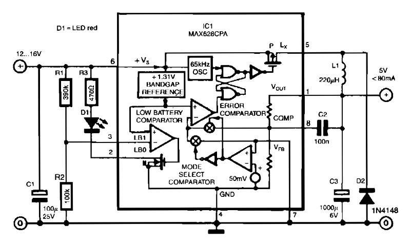
The circuit utilizes the MAX638CPA 5V CMOS Step Down Adjustable Switching Regulator IC, which converts an input voltage of 12 to 16 VDC into a stable 5VDC output. It requires only nine additional external components to complete the circuit....

A Countdown Timer Circuit is a project submitted by a group of students for their ECE 130 - Computer Application class on August 31, 2006, at the University of St. La Salle, Philippines. The seven-segment decoder is utilized in...
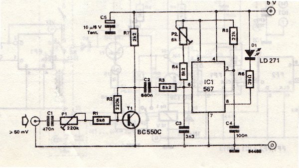
The transmitter is equipped with an LM567 tone decoder circuit. An audio signal (at least 50 mV peak-to-peak) is amplified with a transistor (T1) and then used to modulate IC1. The infrared transmitter frequency is adjusted with potentiometer P2...