
LM567 Infrared Transmitter Circuit

The circuit utilizes the LM567, a versatile tone decoder that can demodulate frequency-modulated signals. The audio input, which must be at least 50 mV peak-to-peak, is first amplified by transistor T1. This amplification stage is crucial for ensuring that the audio signal reaches sufficient levels for effective modulation. The output from T1 is then fed into IC1, which serves as the modulator for the infrared transmission.
The modulation process involves varying the frequency of the infrared light emitted by the transmitter in accordance with the amplified audio signal. The frequency of the infrared transmission can be fine-tuned using potentiometer P2, allowing for adjustments in the range of 25 kHz to 40 kHz. This tunability is essential for optimizing the transmission characteristics based on the specific application requirements, such as distance and clarity.
In terms of circuit design, it is critical to ensure that the power supply for the LM567 and T1 is stable and adequately decoupled to prevent noise from affecting performance. Additionally, the layout should minimize interference and maintain signal integrity, particularly in the modulation stage. Proper component selection for T1, such as choosing a transistor with suitable gain and frequency response, will enhance the overall performance of the transmitter.
The resulting infrared signal can be used for various applications, including remote control systems and wireless audio transmission, making this circuit design both functional and adaptable to different use cases.The transmitter is equiped with LM567, tone decoder circuit. Audio signal ( at least 50mVvv ) is amplified with T1 and then it is used to modulate IC1. Infrared transmitter frequency is adjusted with P2 between 25 and 40KHz. 🔗 External reference
Related Circuits
This timer was designed primarily to turn off a portable radio after a specific duration. This feature allows users to fall asleep on the beach or in a hammock, with the assurance that the radio will automatically shut off...

The circuit depicted in Figure 3-96 features a low-speed operation button (SBz), a high-speed operation button (SBi), and a stop button (SB3). In this configuration, a motor is connected in such a way that when the low-speed button is...
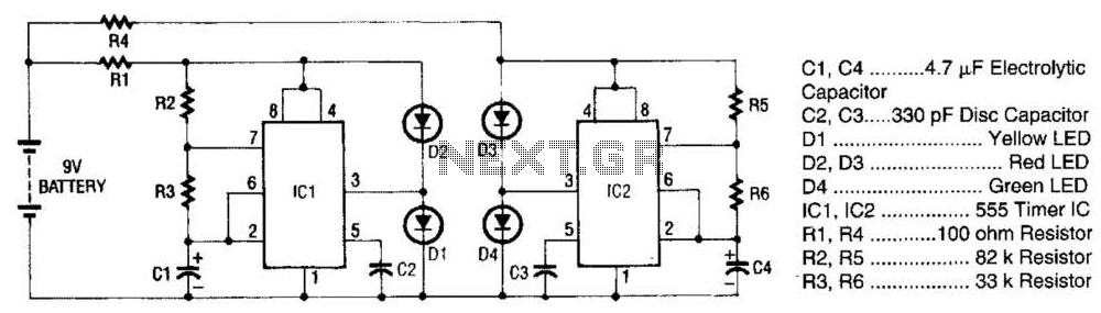
The super LED flasher consists of two complete LED flasher circuits integrated onto a single circuit board. The first LED flasher is comprised of IC1 and LEDs D1 and D2. IC1 is a 555 timer IC configured as an...
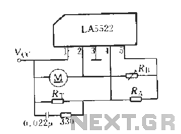
LA5522 Application Circuit. It operates as follows: When the supply voltage (Vcc) changes due to mechanical loads or negative changes, the motor speed may vary. The speed is proportional to the anti-electric potential (E), which also causes changes in...

This figure represents the 4Q2 DC Motor Speed Controller Circuit Block Diagram, designed for comprehensive control of conventional shunt-wound and permanent magnet motors with a capacity of up to 75 kW, as specified in the datasheet. This type of...
The circuit detects a sudden shadow falling on the light-sensor and sounds the bleeper when this happens. The circuit will not respond to gradual changes in brightness to avoid false alarms. The bleeper sounds for only a short time...