
6volt gel cell charger

This circuit design is intended for applications requiring a reliable and efficient charging system. The primary component, a 10V DC power supply, must be capable of providing a steady output of 2 Amps to ensure adequate charging current. The circuit begins charging at a rate of 240mA, which is suitable for initial battery acceptance. Once the battery reaches full charge, the circuit intelligently transitions to a trickle charge mode, reducing the current to 12mA to maintain the battery without overcharging.
The use of capacitors rated for at least 50V is crucial for ensuring the circuit's reliability and longevity, especially under varying load conditions. The choice of the NPN transistor Q1, with its TO-220 package, allows for efficient heat dissipation and robust performance under continuous operation. Alternatives such as the NTE291 and ECG291 provide flexibility in sourcing components while maintaining circuit functionality.
Resistors R4, R5, R6, and R7 are specified as 1% metal film types to ensure precision in the circuit's performance. These resistors play a vital role in setting the charging current and ensuring proper operation of the transistor switch. As these components may not be readily available in all retail outlets, sourcing them from specialized electronic component distributors like Electro-Sonic or Newark Electronics is recommended.
Overall, this circuit design is well-suited for applications that require a precise charging mechanism, with built-in safeguards to prevent overcharging and ensure optimal battery maintenance. Proper selection and sourcing of components are essential for achieving the desired performance and reliability in the charging process.This Circuit needs a adapted 10V-DC advanced end able of bartering 2 Amps. Starts the allegation aeon at 240mA and at abounding allegation switches automatically to a float action (trickle charge) of 12mA. The capacitors are the bowl 50V (or better) type. Switching transistor Q1 is a NPN, Si-Power Output/SW, with a TO-220 case and can be replaced with a acceptable acting like the NTE291, ECG291, etc. Resistors R4, R5, R6, and R7 are 1% metal blur types. They may not be accessible at your bounded Radio Shack/Tandy abundance and accept to be ordered in. Try Electro-Sonic or Newark Electronics accumulation stores. 🔗 External reference
Related Circuits
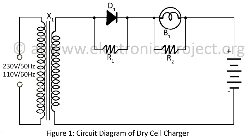
A dry cell charger designed to recharge dry cells 6 to 8 times using a minimal number of components, based on the principle of Periodic Current Reversal (PCR). The circuit diagram is applicable to various projects. The dry cell charger...
Although it does not have the same charm as real mercury barometers with long glass tubes on pieces of carved and polished wood, the Torricelli barometer. The Torricelli barometer, named after the Italian scientist Evangelista Torricelli, is an instrument used...
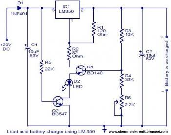
The circuit is designed as a constant voltage source with a negative temperature coefficient. The transistor Q1 (BD 140) serves as the temperature sensor, while transistor Q2 prevents battery discharge through resistor R1 when mains power is unavailable. The...
A simple battery charging circuit is designed using a flyback converter current-limited power supply to charge lead-acid batteries. This circuit is developed by Maxim Integrated. The described battery charging circuit utilizes a flyback converter topology, which is well-suited for applications...
Note first the battery to be treated at the center of the figure. It is connected to contacts of a relay. The diagram shows the relay at rest. Under these conditions the battery is in SHOCK. His pole -...
The following diagram represents the schematic of a Ni-CAD battery charger circuit, which features current and voltage limiting to prolong the battery's lifespan. The lamp L1 will illuminate brightly while the LED will be off when the battery is...