
Dry Cell Charger

The dry cell charger operates on the principle of Periodic Current Reversal (PCR), which enhances the efficiency of the charging process by periodically reversing the current direction. This method helps in reducing the buildup of gas bubbles on the electrode surfaces, which can hinder the charging process and prolong the lifespan of the dry cell.
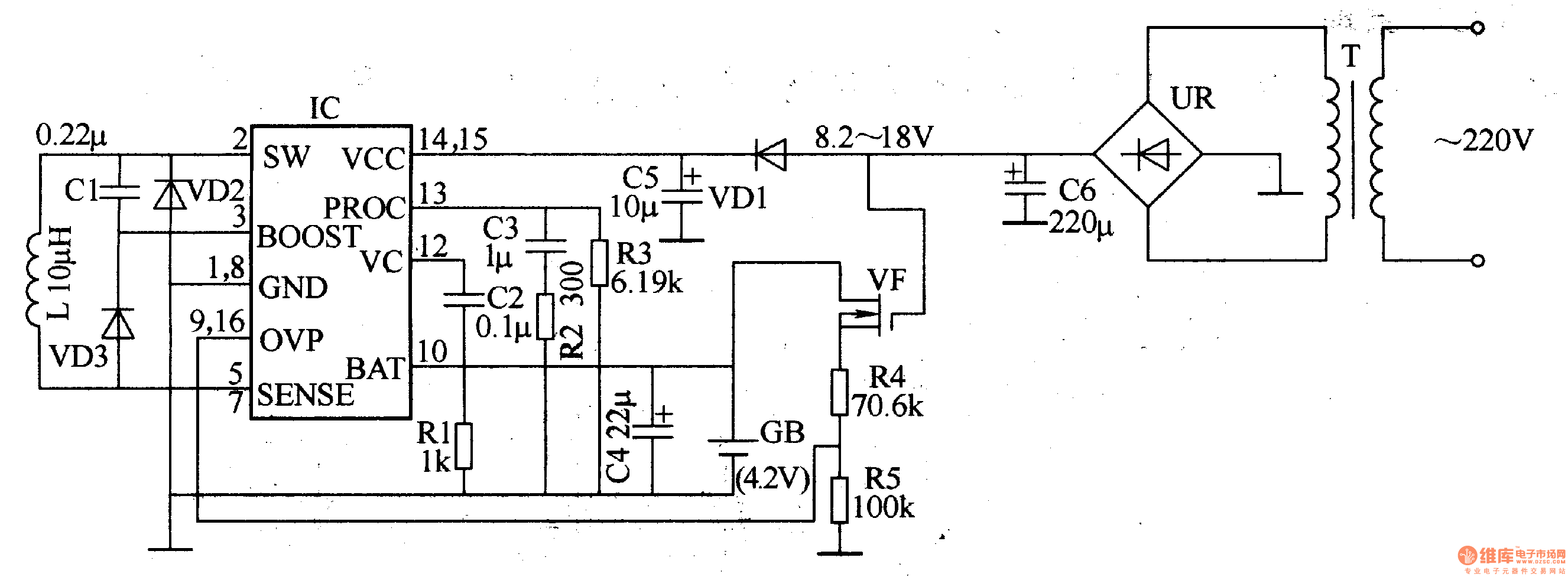
The circuit typically consists of a few key components: a power supply, a switching mechanism, and a control circuit. The power supply provides the necessary voltage and current for charging the dry cell. The switching mechanism, often implemented using transistors or relays, alternates the current flow direction at predetermined intervals. The control circuit may include a timer or microcontroller to manage the switching frequency and duration, ensuring optimal charging conditions.
The schematic diagram for this charger would include the power supply connected to the input of the switching mechanism. The output of the switching mechanism would be linked to the terminals of the dry cell. Additional components such as resistors, capacitors, and diodes may be included to stabilize the circuit and protect against voltage spikes.
This design is particularly advantageous for applications where a reliable and efficient charging method is required without the complexity of larger, more intricate circuits. The use of fewer components not only simplifies the construction but also reduces the overall cost, making it an attractive solution for various DIY projects and practical applications in battery management.Dry Cell Charger utilizing very few component for recharging dry cell 6 to 8 time using principle PCR (Periodic Current Reversal) circuit diagram of various project. 🔗 External reference
Related Circuits
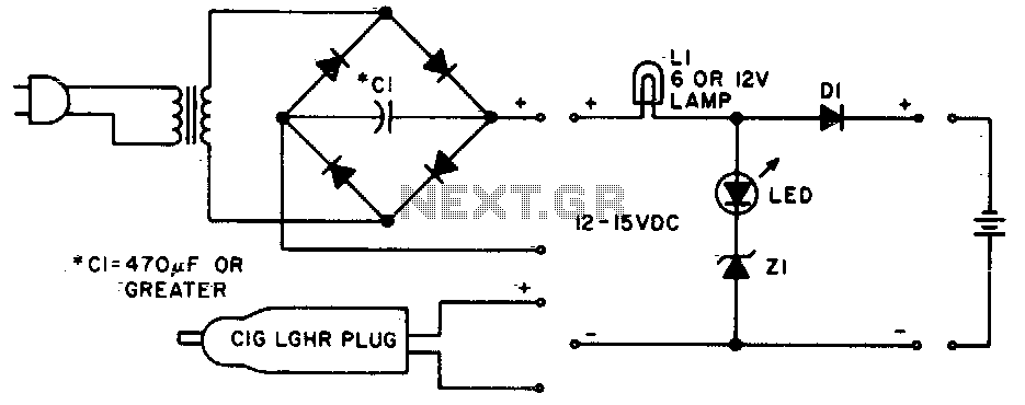
Lamp LI will glow brightly while the LED remains off when the battery is low and charging. Conversely, the LED will illuminate brightly, and the light bulb will be dim when the battery is nearly charged. Lamp LI should...
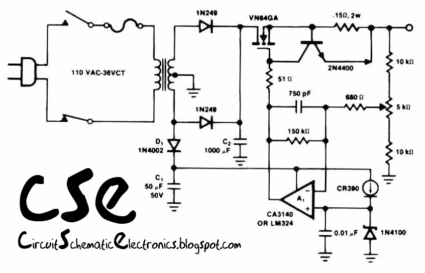
This circuit utilizes the operational amplifier IC LM324 to drive the VN64GA with an error signal and to regulate the output voltage. The output voltage generated is pulsating DC, which is suitable for battery charging applications. Additionally, this circuit...
The ASUS Eee is an exceptional ultra-portable notebook that includes nearly all the necessary features for technology enthusiasts while omitting unnecessary elements. Additionally, it boasts an impressive build quality. The ASUS Eee series is designed with portability and functionality in...
This high-performance circuit first quickly starts (and holds) the charge at 2 amp, but as the voltage rises the current will consequently decrease. When the current falls below 150mA, the charger automatically switches to a lower 'Float' voltage to...
The lithium-ion rechargeable battery charger described in the example operates using a constant voltage and current method. It is designed for charging 3.6V lithium-ion batteries commonly found in various mobile phones. The circuit's working principle involves a battery charger...
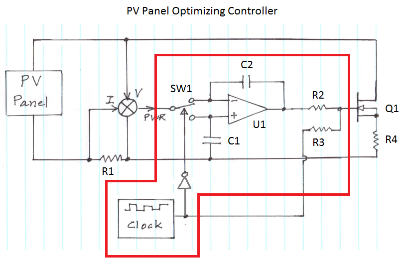
The figure illustrates the voltage-current (V-I) curve for a typical solar panel (Sharp ND-224U1F) and its output power under varying lighting conditions. The solar panel operates as a constant current source at high currents and as a voltage source...