
7-MHz Loop Antenna

The described loop antenna operates effectively by utilizing specific feeding points for either vertical or horizontal polarization, allowing for adaptability depending on the application. The choice of feeding point directly influences the antenna's directivity and radiation pattern, which is critical for achieving optimal performance. The calculated wire length of 141 feet for the loop at 7.125 MHz ensures resonance at this frequency, facilitating efficient radiation.
The matching transformer plays a vital role in impedance matching between the antenna and the transmission line, minimizing signal loss. The length of the matching transformer is determined based on the operating frequency and the velocity factor of the coaxial cable. The formulas provided facilitate precise calculations to ensure the matching transformer is correctly sized for the specific operating conditions. The use of RG-59 coaxial cable, with its velocity factor of 0.66, is a common choice due to its balance of performance and availability.
Additionally, the loop antenna's design allows for versatility in operation across multiple frequency bands, specifically 14 MHz and 21 MHz. This characteristic enhances its utility in various communication applications, making it a valuable component in amateur radio setups and other RF transmission systems. Proper installation and alignment of the antenna are essential to maximize its performance and achieve the desired radiation characteristics.The loop may be fed inside the center of one of the vertical sides if vertical polarization is preferred. For horizontal polarization, it can be necessary to feed either in the horizontal sides in the center.
Optimum directivity happens at proper angles towards the airplane in the loop, or in much more hassle-free terms, broadside through the loop . One need to try to hang the program from on the market supports which will enable the antenna to radiate the utmost amount in some favored path. The overall length of the wire utilized in a loop is determined in ft in the system 1005/f (MHz). Therefore, for operation at seven. 125 MHz the all round wire length are going to be 141 ft. The matching transformer, an electrical 1/4 G« of 75-G™ coax cable, is often computed by dividing 246 by the operating frequency in MHz, then multiplying that amount by the velocity element from the cable becoming utilised.
Therefore, foroperation at 7. 125 MHz, 246/7. 125 MHz = 34. 53 feet. If coax with reliable polyethylene insulation is employed, a velocity issue of 0. 66 have to be employed. Foam-polyethylene coax features a velocity issue of 0. eighty. Assuming RG-59 is utilised, the length of the matching transformer will become 34. 53 (ft). 0. 66 = 22. 79 feet, or 22 ft, 91/2 inches. This same loop antenna may well be used to the 14 and 21-MHz bands 🔗 External reference
Related Circuits
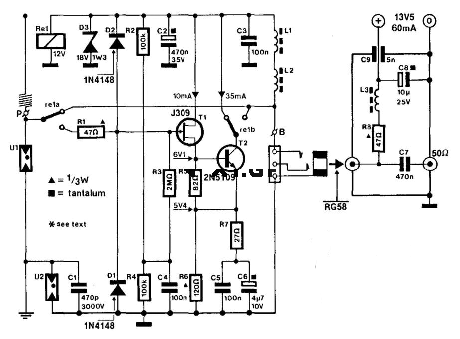
A J309 Siliconix FET is utilized to drive a 2N5109 in a wideband RF amplifier setup. A relay is incorporated to bypass the amplifier in transmit mode, if required. An active antenna element is a 2-meter 5/8-wave whip. The...

This circuit is designed for a UHF TV antenna and provides a 15 dB preamplification. It is constructed using a transistor and minimal components. The schematic features the BF180 UHF transistor. The first stage consists of a band-pass filter...
This is a very simple circuit to interface a current loop sensor to an input which is designed for a voltage, such as that from a standard potentiometer. This page is technical so that interested persons can build the...
The current loop interface is widely used in industrial environments due to its robustness. Its noise resistance and failure detection capabilities make it suitable for various applications. The current loop interface, commonly referred to as a 4-20 mA current loop,...
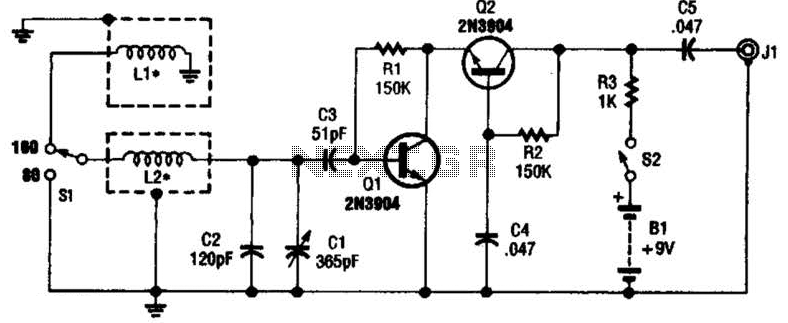
This antenna may assist in minimizing power-line noise. It consists of a plastic hula hoop or conduit with a diameter of 3 feet, which is covered with aluminum foil to serve as a shield for LI and L2. LI...
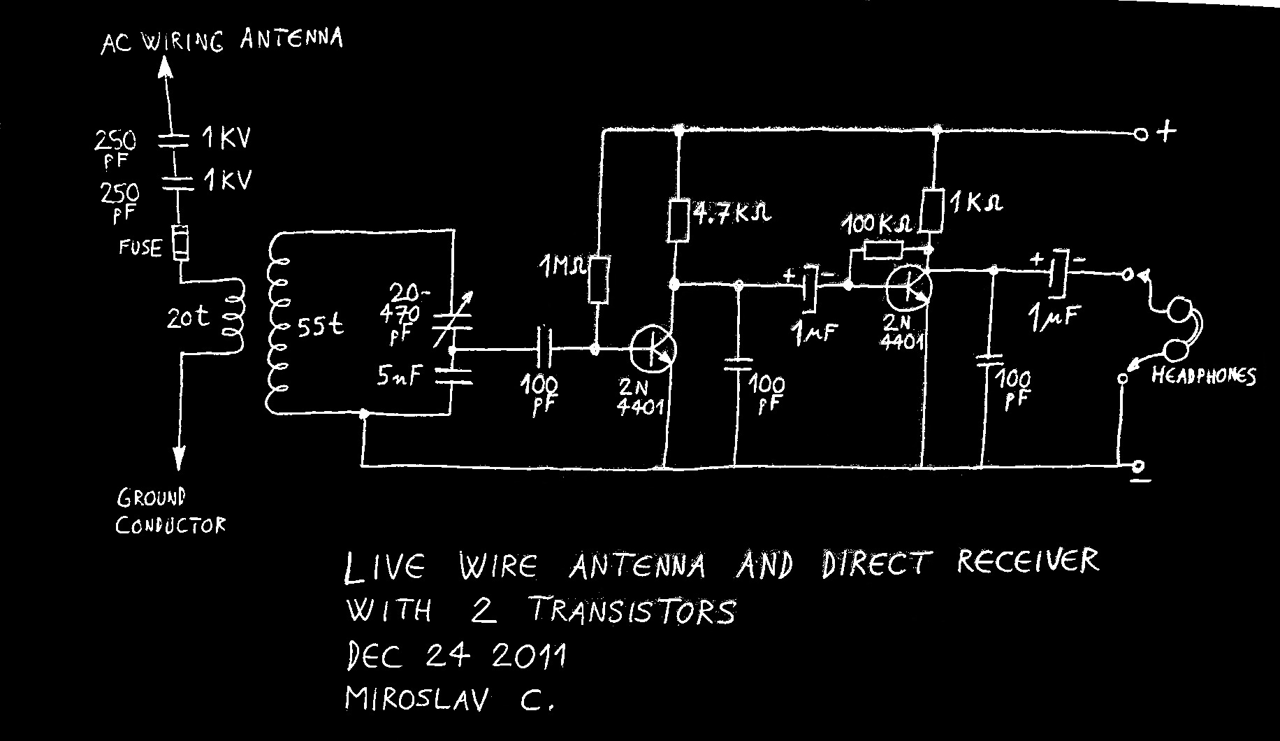
Using live or neutral wire in AC household wiring as a receiving antenna is feasible only with a high-voltage capacitor inserted between the receiver antenna terminal and the live or neutral wire. This AC wiring antenna solution is often...