
15db uhf tv antenna booster circuit

This UHF TV antenna circuit operates by amplifying weak signals received by the antenna, enhancing the overall signal quality for better reception. The circuit's design incorporates a band-pass filter in the first stage, which selectively allows frequencies within a certain range while attenuating out-of-band signals. This helps to improve the signal-to-noise ratio by filtering out unwanted frequencies that could degrade performance.
The components C1, CV1, L1, L4, C7, and C3 are strategically chosen to define the filter's characteristics, such as its center frequency and bandwidth. The air-core coils (L1 to L4) are essential for maintaining a high Q-factor, which is a measure of the filter's selectivity and efficiency. A higher Q-factor indicates that the circuit can more effectively resonate at the desired frequency while rejecting others.
The second stage of the circuit utilizes a base-common voltage amplifier configuration. This configuration is known for its low input impedance, which is beneficial for matching with the output of the band-pass filter. Proper impedance matching is crucial for maximizing power transfer and minimizing reflections that can lead to signal loss.
After the circuit is assembled, it is important to place it inside a metallic enclosure. This not only protects the circuit from physical damage but also shields it from electromagnetic interference (EMI) that could affect performance. By connecting the circuit's ground to the metallic box, any noise picked up by the circuit can be effectively grounded, further enhancing the signal integrity.
Overall, this UHF TV antenna circuit design emphasizes simplicity and efficiency while ensuring optimal performance through careful component selection and layout.This is a circuit for antenna UHF TV that can be give 15dB preamp. This circuit is built by transistor and low components. This is the figure of the circuit. The circuit above is formed based on BF180 UHF Transistor. The first stage is a band pass filter constructed by the C1, CV1, L1, L4, C7 and C3, the second stage is a base-common voltage ampli fier with low input impedance to match. Build the L1 ~ L4 as air core coil to obtain high Q-Factor. After assembling, pack it into a proper metallic box and connect the ground of the circuit to the box to reduce noise effect. 🔗 External reference
Related Circuits
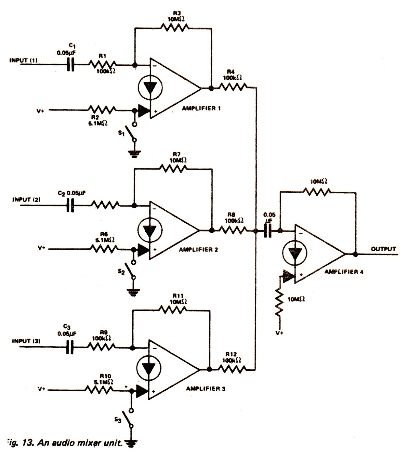
The amplifiers of an LM3900N device can be utilized to create an audio mixer unit that allows for the combination of three separate audio signals into a single composite output. The audio mixer circuit provided operates with a single...
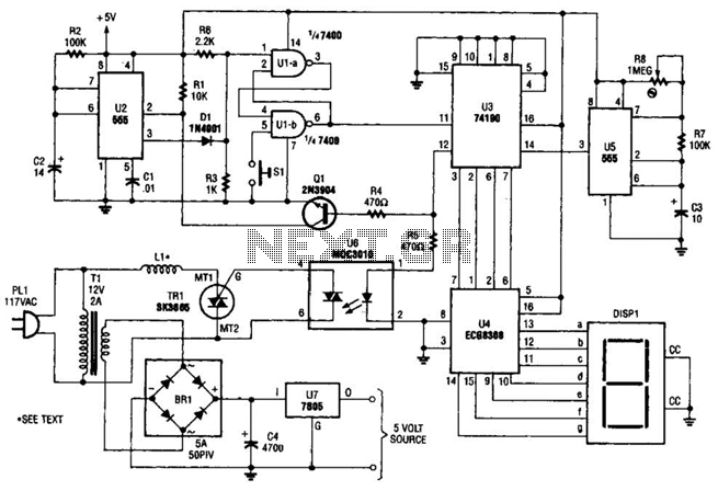
The electromagnetic ring launcher consists of four subcircuits: a clock circuit utilizing U5, a 555 oscillator/timer configured for astable operation; a countdown/display circuit incorporating U3, a 74190 synchronous up/down counter with BCD outputs set for countdown operation; U4, an...
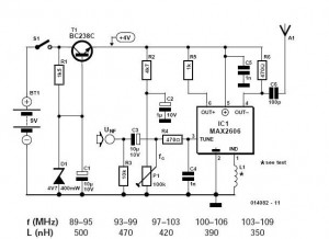
These do-it-yourself FM transmitters are relatively simple to construct and provide a satisfying experience when music is played through the radio receiver. Comments and links to additional designs that are not included in the best list are welcome. FM transmitters...
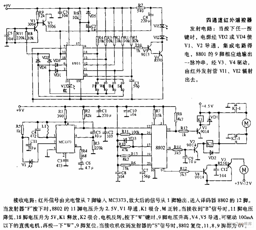
The receiving circuit involves an infrared signal being input to the MC3373 from pin 7 via a phototube. The amplified signal is output from pin 1 and sent to pin 12 of the decoder 8802. When the transmitter F...
The SC41343 is designed as a type of infrared, ultrasonic, or RF remote control launch coding circuit. The internal circuit comprises a sequence generator, control logic circuit, 4-bit shift register, data extraction circuit, and latch circuit. Features include the...
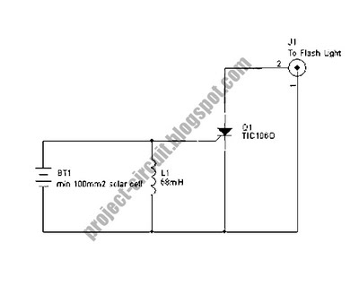
The following circuit illustrates a Slave Flash Light Control Circuit Diagram. Features include a 68 mH inductor, which provides an automatic trigger for the secondary flash light. The Slave Flash Light Control Circuit is designed to enhance the functionality of...