
7 segment led counter

The described counter circuit is a versatile electronic device designed for counting applications. It operates on Transistor-Transistor Logic (TTL) levels, making it suitable for integration into various digital systems. The primary function of the counter is to increment its count in response to incoming pulses, which can originate from various sources such as sensors, switches, or other digital circuits.
The basic architecture of the counter typically includes a flip-flop or a series of flip-flops configured in a binary counting arrangement. Each pulse received at the input toggles the state of the flip-flops, resulting in a binary count that can be displayed or processed further. The circuit can be designed to count up or down, depending on the configuration of the control signals.
For expansion, additional flip-flops can be cascaded to increase the counting capacity. For example, a 4-bit counter can count from 0 to 15, while an 8-bit counter can extend this range to 0-255. The circuit may also include features such as reset functionality, allowing the count to be set back to zero at any point, and enable/disable controls to manage when the counting should occur.
In practical applications, the output of the counter can be interfaced with various display technologies, such as seven-segment displays or LCDs, to provide a visual representation of the count. Furthermore, the circuit can be integrated with microcontrollers or other digital logic devices for more complex counting tasks, such as event logging or data acquisition.
Overall, this simple counter circuit is a fundamental building block in digital electronics, providing essential counting capabilities for a wide range of applications.This simple counter can be used to count pulses, as the basis for a customer counter (like you see at the doors of some stores), or for anything else that may be counted. The circuit accepts any TTL compatible logic signal, and can be expanded easily 🔗 External reference
Related Circuits
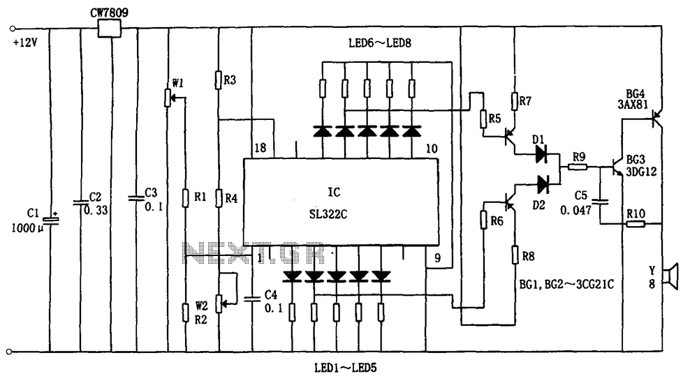
The circuit illustrated in the figure is a hydraulic oil level alarm system for automotive applications. It consists of a light-emitting diode (LED) driver, the SL322C integrated circuit (IC), a voltage regulator circuit (CW7809), and hydraulic oil level sensors...
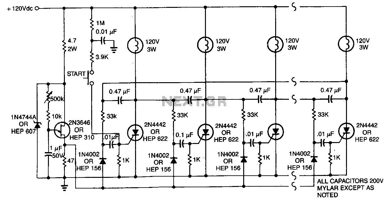
One lamp at a time is lit in the string to give the appearance of a moving point of light. More: The ring counter circuit. The described circuit utilizes a ring counter configuration to create a sequential lighting effect in...
The microcontroller unit (MCU) will read images from the DataFlash memory via the SPI bus based on the known velocity. It will then send these images to the LED drivers using the SPI bus, controlling the on and off...
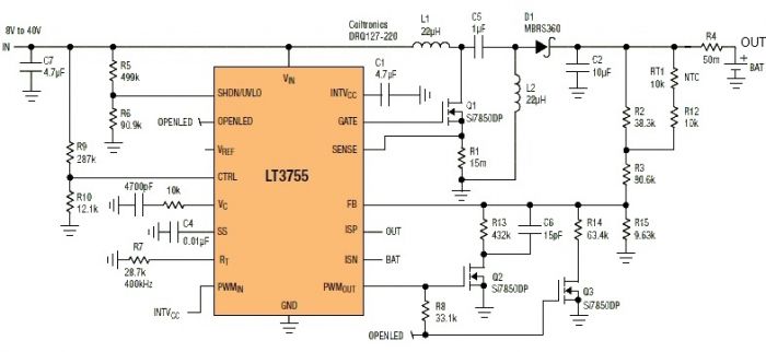
This Sealed Lead Acid Battery Charger is designed using the LT3755 DC-DC controller. The LT3755 is a DC-DC controller that operates as a constant-current source and supports a wide input voltage range from 4.5 to 40 volts, providing a...
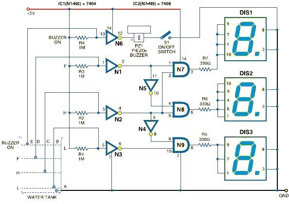
This schematic outlines a simple electronic circuit designed to indicate water levels using a 7-segment display. The circuit shows water levels by displaying 'L', 'H', and 'F' for low, half, and full levels, respectively. It is based on the...
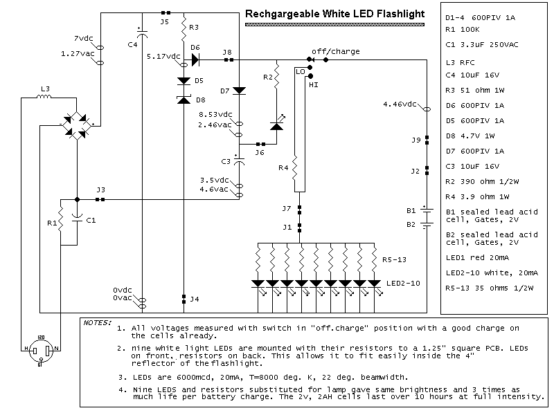
Here is a schematic of a rechargeable 9-LED flashlight using two Gates SLA cells and nine LEDs. It is as bright as when the single bulb was used, and lasts 3 times longer per charge. That is about 10...