
Bicycle LED POV hardware

The described circuit operates by integrating several key components to achieve the desired functionality of LED control based on data stored in memory. The microcontroller unit (MCU) serves as the central processing unit, orchestrating the timing and control signals necessary for the system's operation. It communicates with the DataFlash memory using the Serial Peripheral Interface (SPI) bus, a synchronous serial communication protocol that allows for high-speed data transfer.
The MCU is programmed to sample the velocity of the system, which serves as a trigger for reading specific images stored in the DataFlash memory. Upon receiving the velocity data, the MCU initiates a read sequence from the DataFlash, retrieving the relevant image data. This data is then transmitted to the LED drivers, also over the SPI bus. The LED drivers are responsible for controlling the individual LEDs, turning them on and off as dictated by the image data received from the MCU.
Powering the LED drivers is crucial for their operation. In this design, the LED drivers are directly powered by the voltage supplied from two cells, ensuring that they receive sufficient current to drive the LEDs effectively. The choice of two cells suggests a battery-operated system, where the voltage output must be managed carefully to prevent damage to the LEDs.
Additionally, the system incorporates a DC-DC converter circuit, which steps down or regulates the voltage to provide a stable +3.3 volts supply. This voltage is essential for powering the MCU, DataFlash memory, and the Hall effect sensor, which may be used for detecting position or motion within the system. The DC-DC circuit ensures that all components receive the proper operating voltage, enhancing the reliability and performance of the overall system.
In summary, this electronic schematic integrates an MCU, DataFlash memory, LED drivers, and a DC-DC power supply to create a responsive LED control system based on velocity data. Each component plays a vital role in ensuring that the system operates efficiently and effectively.Knowing the velocity, MCU will read the images from the DataFlash memory using SPI bus, and in the correct timing will send them to the LED drivers using SPI bus, turning on and off the LEDs. The voltage of 2 cells will drive directly the LEDs drivers. +3. 3 volts are available for to use by MCU, DataFlash memory and the hall effect sensor, thanks to DC-DC circuit. 🔗 External reference
Related Circuits
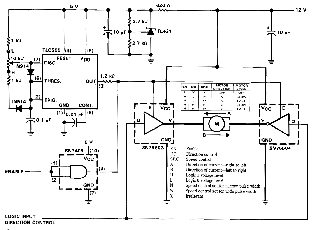
The figure illustrates a reversible DC motor drive application with adjustable speed control. The D inputs for these drivers are complementary and can be tied together and driven from the same logic control for bidirectional motor drive. The enables...
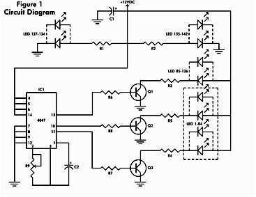
It consists of a 4047 low-power monostable/astable multivibrator, IC1, used in the astable mode to provide the timing pulses to control the flash rate of the LEDs. To accomplish the astable mode, pins 4, 5, 6, and 14 are...
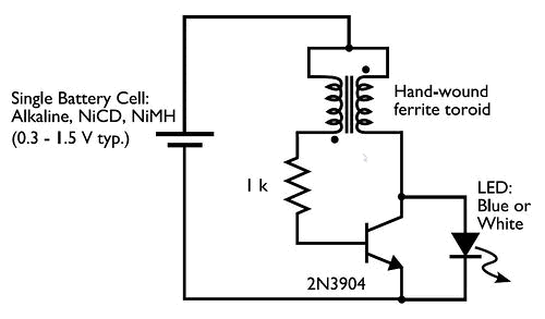
Concerned about darkness? Constructed a basic Joule Thief circuit and wish to advance further? Seeking a striking blue light to impress friends? Introducing the Joule Thief 10x10 LED Lamp! This device operates on one to four AA batteries and...
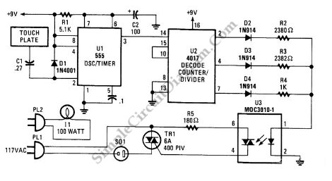
This is a three-mode lamp dimmer circuit with touch control. This circuit can be used to control a lamp in three operation modes: dim, off, and bright. A NE555 timer is utilized in the design. The three-mode lamp dimmer circuit...
The circuit was designed to work with an audio power amplifier which operated off +18v-0v-18v power rails. The actual voltage used is not too critical except that the feedback is referred to the LED chain which itself is anchored...
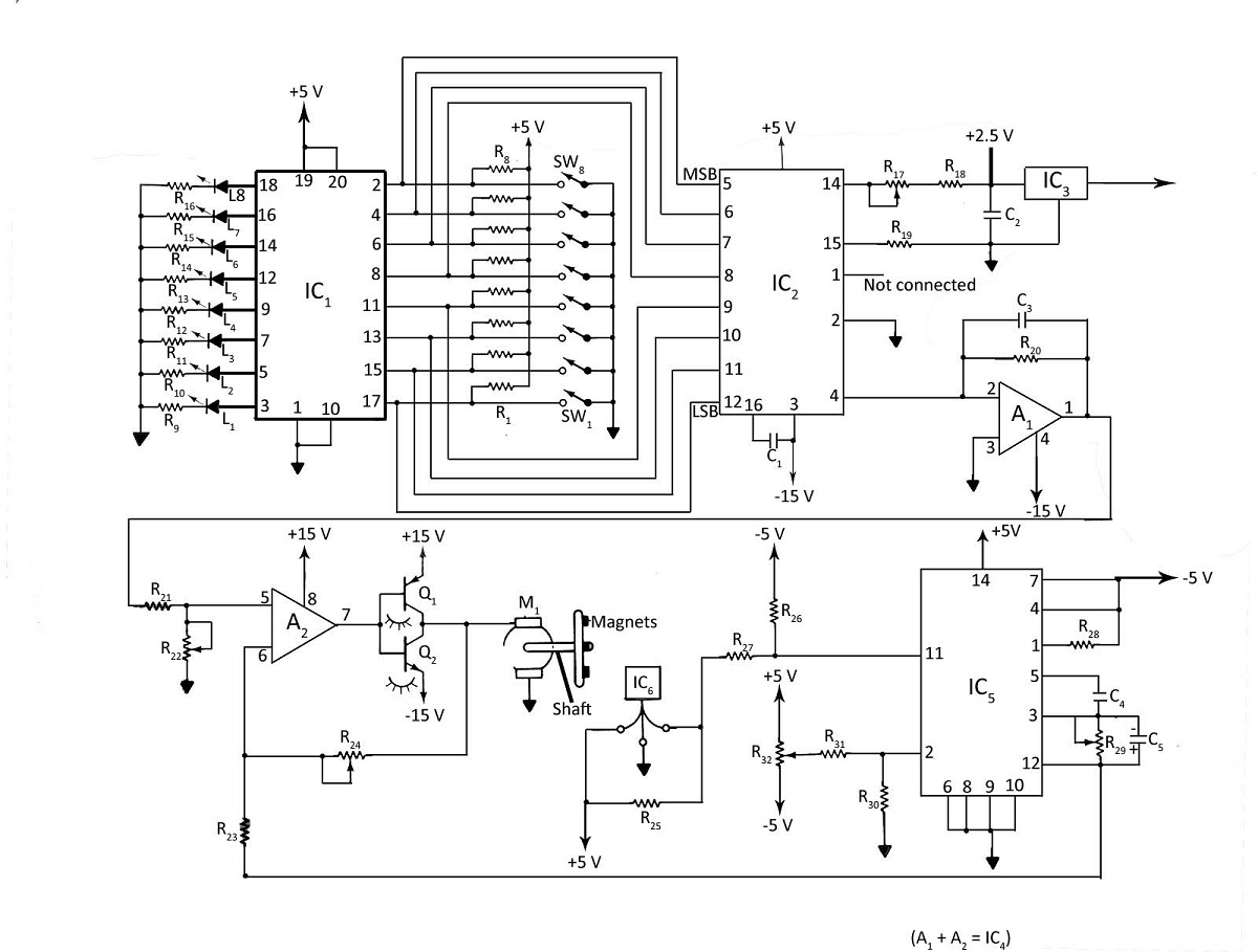
Various techniques can be employed to control the speed of a DC motor, including phase-locked-loop principles, digital inputs, or analog inputs. Additionally, the motor's speed can be monitored using LED or LCD displays. The digital DC motor speed controller...