
7-Segment (Led) Display Driver Circuit
 Display Driver")
The 7447 integrated circuit is a BCD to 7-segment decoder/driver that converts binary-coded decimal (BCD) inputs into the corresponding output signals that illuminate specific segments of a 7-segment display. In a common anode configuration, the anode of each LED segment is connected to a positive voltage supply, while the cathodes are connected to the output pins of the 7447 IC. When the output of the IC goes low, it allows current to flow through the respective segment, lighting it up.
To ensure proper operation and prevent damage to the LED segments, a current-limiting resistor (R) is necessary. The resistor value can be calculated using Ohm's law and the specifications of the LED display. The maximum forward voltage (Vf) of the segments and the supply voltage (Vs) must be taken into account. The formula to calculate the resistor value is:
R = (Vs - Vf) / If
Where:
- R is the resistance in ohms (Ω),
- Vs is the supply voltage in volts (V),
- Vf is the forward voltage drop across the LED segment in volts (V),
- If is the desired forward current through the LED segment in amperes (A).
For example, if the supply voltage is 5V, the forward voltage drop of the LED is 2V, and the desired forward current is 20mA (0.02A), the calculation would be:
R = (5V - 2V) / 0.02A = 150Ω
This means a 150Ω resistor should be used to limit the current through each segment to the rated value, ensuring optimal performance and longevity of the LED display. Proper selection of the resistor is critical in applications where variations in supply voltage may occur, as it helps maintain consistent brightness and prevents excessive current that could potentially damage the LEDs. An IC1 like a 7447 drives a 7-segment common anode LED display. Current, limiting resistor R should limit the segment current to the rated value at maximum supply voltage. A sample calculation is shown.
Related Circuits
This circuit is designed for use with inductive pick-up elements and dynamic microphones. Most soundcards feature a line input and a separate input for electret (condenser) microphones. To connect an inductive tape recorder head or a dynamic microphone, an...
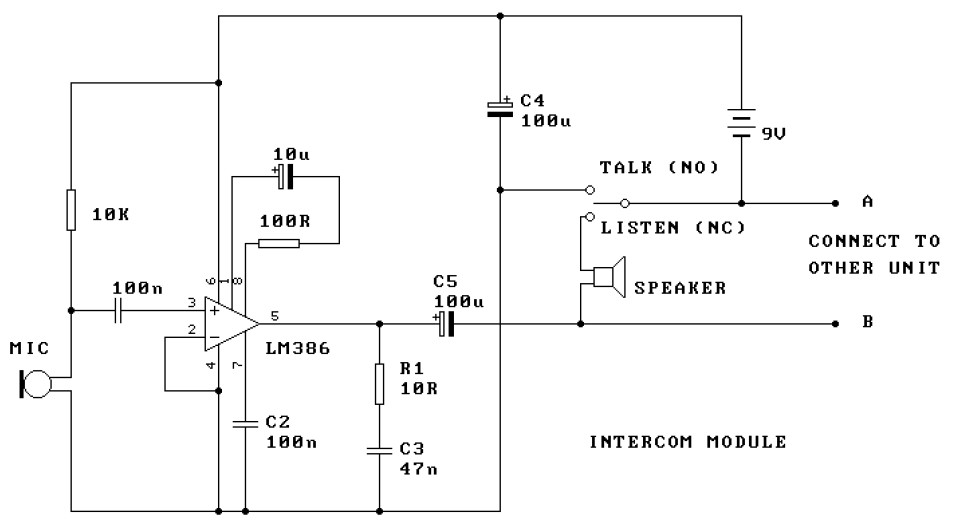
This is a two-station intercom system that operates using two wires connecting each intercom unit. Each unit is self-contained, equipped with its own battery, speaker, microphone, and amplifier circuit. An LM386 audio power amplifier is utilized, which is widely...
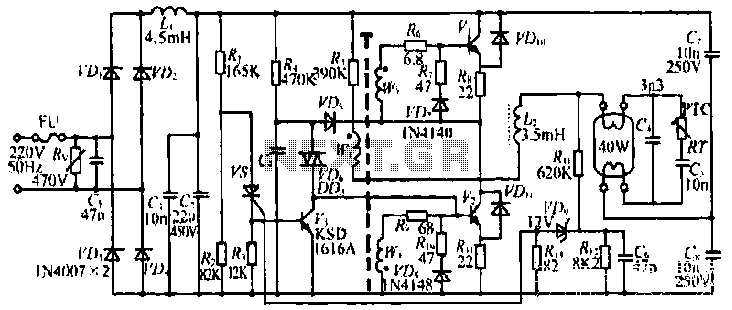
The figure illustrates the input from the varistor, which serves an overvoltage protection role. Components VDi and VD4 function as rectifiers, while L1 and C2 are utilized for filtering. The circuit comprises R, C9, and VD6, which are part...
A single-chip metal detector with a detection range of a few inches. This device is useful for identifying nails or screws in walls and floors, as well as locating buried mains cables. The core of the metal detector circuit...
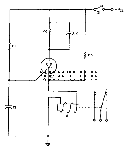
The relay operates for a specific duration, td, after power is applied, followed by an operating time, tc. The SCR activates when the voltage across capacitor Ci reaches a threshold voltage, VA. This action energizes the relay, which remains...
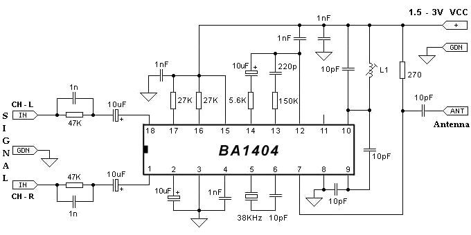
The BA1404 can be utilized to create a simple and effective FM stereo modulator electronic project. This BA1404 FM stereo modulator device operates within the FM broadcast band (75-108 MHz) and requires only a few common external components. The...