
BA1404 FM Stereo modulator circuit design electronic project

The BA1404 FM stereo modulator is designed for applications in the FM broadcast band, making it suitable for amateur radio projects and personal audio transmission systems. The circuit primarily consists of the BA1404 IC, which integrates several functions, thereby reducing the number of external components required for operation.
The stereo modulator within the BA1404 creates composite audio signals by combining the left (L) and right (R) audio channels. This process produces a main signal (L+R) and a sub signal (L-R), which are essential for stereo sound reproduction. The pilot signal, generated at 19 kHz, serves as a synchronization reference for FM receivers, ensuring proper demodulation of the stereo signal.
The FM modulator section of the BA1404 takes the composite signals and modulates them onto a carrier frequency within the FM broadcast band. This modulation process enables the transmission of audio signals over the airwaves, allowing for wireless audio broadcasting. The RF amplifier enhances the output signal, ensuring sufficient power for effective transmission distance.
To implement this circuit, a 38 kHz crystal oscillator is required, which provides stability and precision in frequency generation. The choice of external components, such as capacitors and resistors, will influence the performance of the transmitter, including frequency stability and modulation depth. Proper layout and shielding are also critical to minimize interference and ensure clear audio quality.
Overall, the BA1404 FM stereo modulator is an efficient solution for creating a compact FM transmitter capable of delivering high-quality stereo audio signals. Its simplicity and integration of multiple functions make it an attractive choice for hobbyists and engineers working in the field of wireless audio transmission.Using BA1404 can be designed a very simple and useful fm stereo modulator electronic project. This BA1404 fm stereo modulator device works in FM broadcast band ( 75- 108MHz) and require few external common components. The BA1404 fm stereo modulator Ic contains all parts needed to design an simple high efficiency stereo transmitter circuit.
This IC contains a stereo modulator that creates stereo composites signals, an FM modulator that creates FM signals and a RF amplifier. The fm stereo transmitter develops composite signals made up of a main(L+R) signal and sub(L-R) signal and a pilot (19KHz) signal using a 38KHz crystal oscillators.
🔗 External reference
Related Circuits
Dark Activated Switch or Porch Light Switch. This circuit activates a relay when the light level drops below a preset threshold. The light sensitivity can be adjusted using variable resistor VR1, and the relay contacts can control an external...

A DC brush motor driver circuit diagram utilizing the MC33035 chip is presented, illustrating a typical configuration for driving a straight DC brush motor. The circuit incorporates a field-effect transistor (FET) bridge driver setup. When transistor VT3 is activated,...
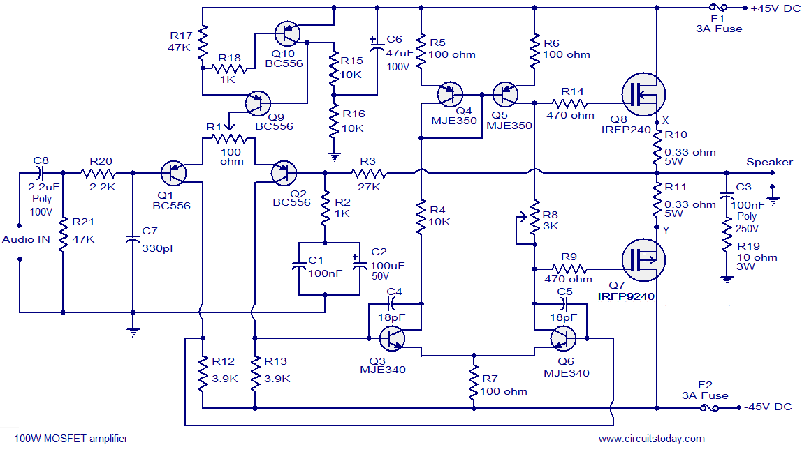
Hi-fi 100W MOSFET power amplifier circuit. Operates from a 45V dual supply. Delivers 100W to an 8-ohm speaker and 160W to a 4-ohm speaker, with low distortion. The Hi-fi 100W MOSFET power amplifier circuit is designed to provide high-quality audio...
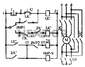
Motor windings are set to connect in a Y configuration while the load is active. The system includes an electric suction mechanism, and the motor is designed to operate under specific conditions. It is rated for 600 revolutions per...
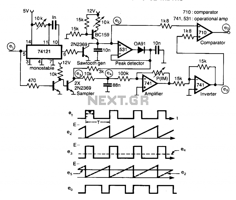
A circuit designed to multiply the width of incoming pulses by a factor that can be greater or less than unity is straightforward to construct. It features a single adjustable potentiometer for selecting the multiplying factor. This factor is...
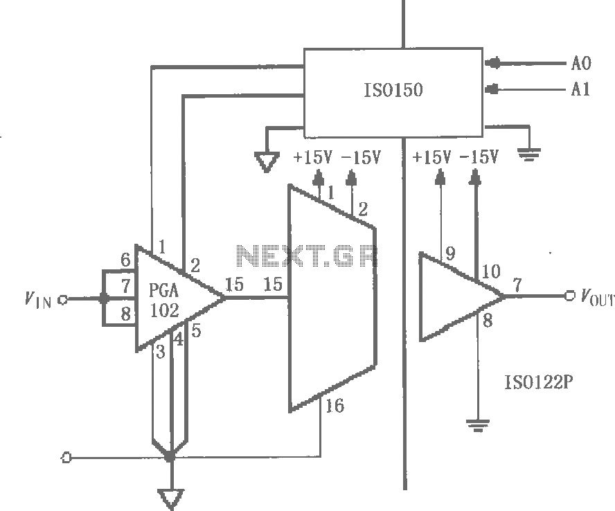
The circuit features grounds ISO122/124 and PGA102, with ISO150 forming a gain programmable channel isolation circuit. The input signal VIN is amplified by the instrumentation amplifier PGA102 to ISO122P, which then outputs VOUT from the isolation amplifier ISO102P. Two...