
70 MHz Transverter

The transverter design integrates various electronic components to facilitate efficient operation in the specified frequency range. The use of high-power microwave transistors allows for a robust design that can handle the required output power while maintaining performance. The choice of a finned heat sink (HS115-150) ensures adequate thermal management, critical for high-power applications. The layout of the three printed circuit boards is optimized for space and functionality, ensuring that all components are easily accessible for maintenance and adjustment.
The tuning process is critical for ensuring that the transverter operates within the desired frequency range. It involves careful adjustment of the variable capacitors and inductors, with attention paid to the interaction between components to avoid self-excitation and ensure stable operation. The use of salvaged components from existing radios not only provides cost savings but also encourages creativity in utilizing available resources effectively.
The design also emphasizes the importance of shielding and grounding to reduce interference and improve signal quality. The strategic placement of coils and the use of screens help mitigate inductive coupling, which can adversely affect performance. The careful consideration of component placement and the overall assembly of the transverter contributes to its reliability and efficiency in operation. This transverter project exemplifies the principles of electronic design, integrating various elements to achieve a functional and effective communication device.A transverter on a range of 70 MHz. With access to the transceiver KENWOOD TR-751A (144 - 146 MHz), which was already prepared to work with the transverter DB6NT 5. 6 and 10 GHz, ie, output power is reduced to 1 watt, and transfer to the central core of coaxial transmission appears + 12 volts, I decided it was under him and make up to 70 MHz transverter.
Block diagram of the transverter shown in the figure located in the following, where I tried to define in detail what the active element is used for what. Also shown in this figure reached my level of useful signal. The scheme of the transmitter power amplifier "PA". Initially, I wanted to do a power amplifier using module MITSUBISHI RA30H0608M, but having in the presence of a large number of high-power microwave transistors Soviet-made, I got an interesting design, assemble and adjust the amplifier is shown in the diagram on the elements.
Tinkered with every denomination scheme. Construction. The basis for the boxes, as well as cooler, finned heat sink is HS115-150, bought by me here. It was convenient because it already has holes for mounting the front and back panels. All parts, except for the indicator, power button, LEDs, relays, and an antenna connector, assembled on three printed circuit boards. Fees blocks "LO" and "Main" mounted above the radiator on the rack height of 5 mm. Details and winding products. Most denominations used parts, specified in the above schemes. One of the problems in the design of this design was the use of those components, which "are at hand".
Purchased items were assumed to be only on the condition that they are either facilitate or simplify a very, or decorate, etc. construction. L23 and L24 coils are taken from the receiving channel radio DRAGON SY-252N, but they can make and myself, 2 + 2 turns on the frame 5 mm in diameter with a core of ferrite.
The picture detail frame with a screen that shows the right. At the same pictures you can see the variable capacitors are applied by me, because I do not know their type. Green is 1-30 pF capacitor, and white - 6-80 pF. Coil L8, L9, L18, L20, L21, L22 are wound with 10 turns and wire diameter of 0. 8 mm mandrel diameter of 5 mm, with winding length of 12 mm. Removal of some of these coils is made of 3, starting from the output of the RF grounding, turn. The coils L12, L13 and L15 are wound the same as the previous coil wire on the same mandrel, and are 7, 5 and 3 turns.
Between the coils L8 and L9 a screen made of tinned steel. From the same plate screens are made of coils L20 - L22, excluding the inductive coupling between the coils and other elements of the scheme. Coils and chokes included in the block "PA", and preferably all other parts of this unit should be pressed as close as possible to the board, eliminating the possibility of self-excitation of the block.
Tuning. Setup begins by checking transverter operation of the circuit RX / TX. Closing the contacts "PTT", check the appearance of voltage + 12 V at the outputs of "T" and "R" block "LO", the translation transverter mode transmission and reception, respectively. Then set the voltage on the findings of transistor dc mentioned in the scheme. Short the crystal constant capacitor capacitance 10nF and connecting to the lower frequency of the scheme concluded coil L10, twist core coils L7, L10 until the frequency meter readings will not be equal to approximately 25 MHz.
After that, disconnect the capacitor shorting crystal. Following the frequency of which should be in the range of 75 MHz, adjust capacitors C18 and C20 trying to get t 🔗 External reference
Related Circuits
During a 50MHz SSB-QSO, my friend JE3TXU/1 (Mr. Haraguchi) mentioned that he had created a very compact 50MHz transceiver. I suggested that he should share this information in the Japanese CQ magazine. Additional details can be found in a...
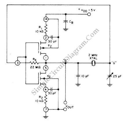
This circuit is a 2 MHz crystal oscillator utilizing a CMOS transistor pair. It is particularly suitable for applications in digital watches and clocks due to its low power consumption. The oscillator is constructed by connecting a CMOS transistor...
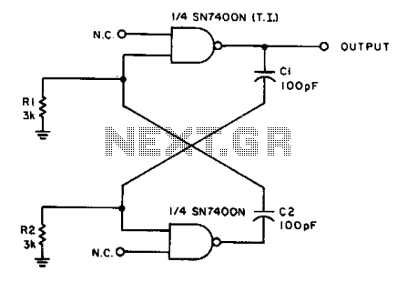
With the values shown, the circuit generates a 2-MHz symmetrical square wave. Changing capacitors C1 and C2 to 0.01 µF results in a frequency of 500 Hz. For the particular integrated circuits and power supply voltages (5.0 V), the...
By using transformers, both voltage feedback and current feedback can be applied. An article by DJ2LR Ulrich Rohde in Ham Radio, November 1979, provides details about this circuit. For the 2.5 MHz to audio converter, the transformation ratio from...
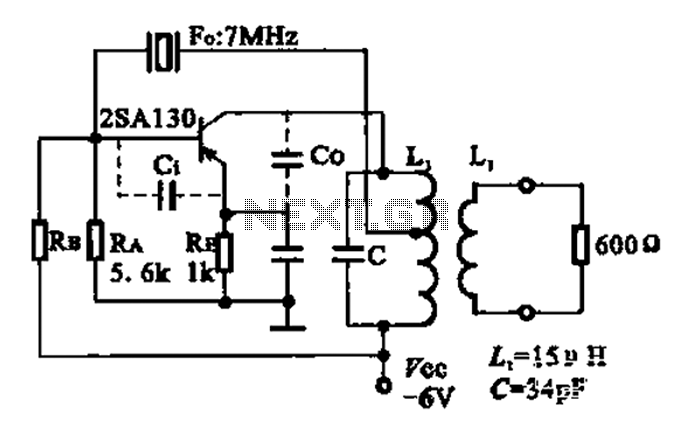
The 2SA130 transistor is used in an oscillator circuit with an oscillation frequency of 7 MHz. The power supply voltage is 6V, and the load is a frequency-selective resonant circuit with a quality factor of 600. The circuit utilizes the...

This design circuit is for a simple 27MHz transmitter that produces a carrier signal. The circuit generates an unmodulated 27MHz signal, which can be received by a compatible receiver. The transmitter operates as a basic crystal oscillator, with the...