
7MHz high frequency carrier oscillator

The circuit utilizes the 2SA130 transistor, a general-purpose NPN transistor, to create a high-frequency oscillator. In this configuration, the transistor is biased to operate in the active region, allowing it to amplify signals and sustain oscillations. The oscillation frequency of 7 MHz is determined primarily by the reactive components in the circuit, which typically include capacitors and inductors.
The power supply voltage of 6V is suitable for the 2SA130, as it can handle a maximum collector-emitter voltage of 50V, providing ample headroom for stable operation. The frequency-selective resonant circuit, characterized by a quality factor (Q) of 600, indicates a highly selective response to the oscillation frequency. A high Q factor suggests that the circuit has a narrow bandwidth, allowing it to filter out unwanted frequencies effectively while maintaining a strong response at the desired frequency of 7 MHz.
The resonant circuit can be implemented using a combination of inductors and capacitors arranged in a tank circuit configuration. The inductor and capacitor values must be chosen carefully to achieve the desired resonant frequency, which can be calculated using the formula:
\[ f = \frac{1}{2\pi\sqrt{LC}} \]
where \( f \) is the resonant frequency, \( L \) is the inductance in henries, and \( C \) is the capacitance in farads. The high Q factor indicates that the circuit will have minimal energy loss, making it suitable for applications requiring precise frequency generation, such as RF transmitters and receivers.
In summary, this oscillator circuit with the 2SA130 transistor is designed for efficient operation at 7 MHz, powered by a 6V supply, and utilizes a resonant circuit with a high quality factor to achieve selective frequency response. Proper component selection and circuit design are critical to ensure stable oscillation and desired performance characteristics.2SA130 transistor shown oscillator, the oscillation frequency of 7 MHz, the power supply voltage is 6V, frequency-selective resonant circuit load 600 Q.
Related Circuits
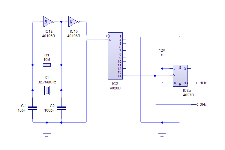
This plugin utilizes a quartz oscillator featuring a crystal (X1) to produce a 32,768 Hz (32,768 = 2^15) output. This frequency is fed into a 4020 14-Stage Ripple Counter, which divides the signal by 2^14, resulting in a 2...

This circuit is a Flasher that directly derives power from AC to produce brilliant flashes at a rate of one flash per second. It utilizes a Diac as the primary element. The Flasher circuit operates by converting alternating current (AC)...
This circuit generates a low power test signal and should not be used as a transmitter. Make sure you are within the law in the locality in which you operate this. As this was built from parts laying on...
An audio test oscillator circuit typically produces a square wave if the oscillation frequency is low enough in relation to the amplifier's bandwidth. This circuit features a crystal-controlled oscillator designed for low-frequency sine wave generation, characterized by low distortion,...
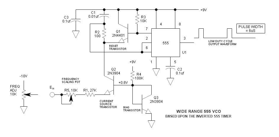
The frequency of the 555 timer can be adjusted by changing the voltage at pin 5. However, the range and linearity of this adjustment are quite limited. This can be significantly improved by using an inverted 555 timer circuit....
A useful marker oscillator can be constructed using an NE555 timer to generate pulses at an audio frequency. This design facilitates the detection of the signal even amidst interference. The crystal frequency can range from 1 to 30 MHz. The...