
70Mhz Rf Power Amplifier Circuit

The SD1143 transistor is a high-frequency device that excels in low-frequency applications, making it suitable for various amplification tasks. In this circuit configuration, the transistor operates within its optimal gain range, leveraging its characteristics to enhance signal strength effectively. The 14 dB gain indicates that the output signal is 14 times more powerful than the input, which is critical for applications needing robust signal amplification.
The circuit is designed to take a modest input power of 300 to 500 mW and amplify it to a substantial output power of 8 to 10 W. This level of amplification is particularly beneficial in transverter applications, where the signal must be boosted before transmission or further processing. The efficiency of the SD1143 in this role allows for effective communication over extended distances, making it an essential component in RF (radio frequency) systems.
The design considerations for this circuit include the careful selection of passive components, such as resistors and capacitors, to ensure stability and minimize distortion. Proper biasing of the transistor is also crucial to maintain linear operation and prevent thermal runaway. Additionally, attention must be paid to the layout of the circuit to reduce parasitic inductance and capacitance, which can adversely affect performance at higher frequencies.
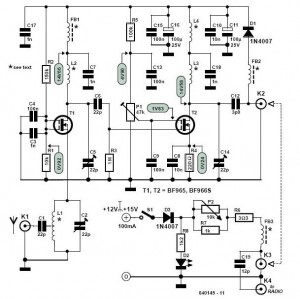
Thermal management is another important aspect of the circuit design, as the transistor will generate heat during operation. Adequate heat sinking and ventilation must be implemented to ensure reliable operation and longevity of the SD1143 transistor within the circuit. Overall, this amplifier circuit represents a well-engineered solution for achieving significant power amplification in RF applications. The SD1143 transistor provides a gain of about 14 dB in this circuit. It uses the fact that a 175-MHz device has a much higher gain when used at lower frequencies. The amplifier was originally designed to be used with a transverter. The output is 8 to 10 W for a 300- to 500-mW input.
Related Circuits
Along with a suitable directional antenna, this high-performance two-stage antenna amplifier for the VHF FM broadcast band will allow for the reception of distant signals. This two-stage antenna amplifier is designed to enhance signal reception in the VHF FM broadcast...
Using high-beam headlights can significantly enhance visibility while driving, but they can also pose a blinding hazard to other drivers. A simple circuit can be integrated into the headlight system to enable automatic switching between high and low beam...
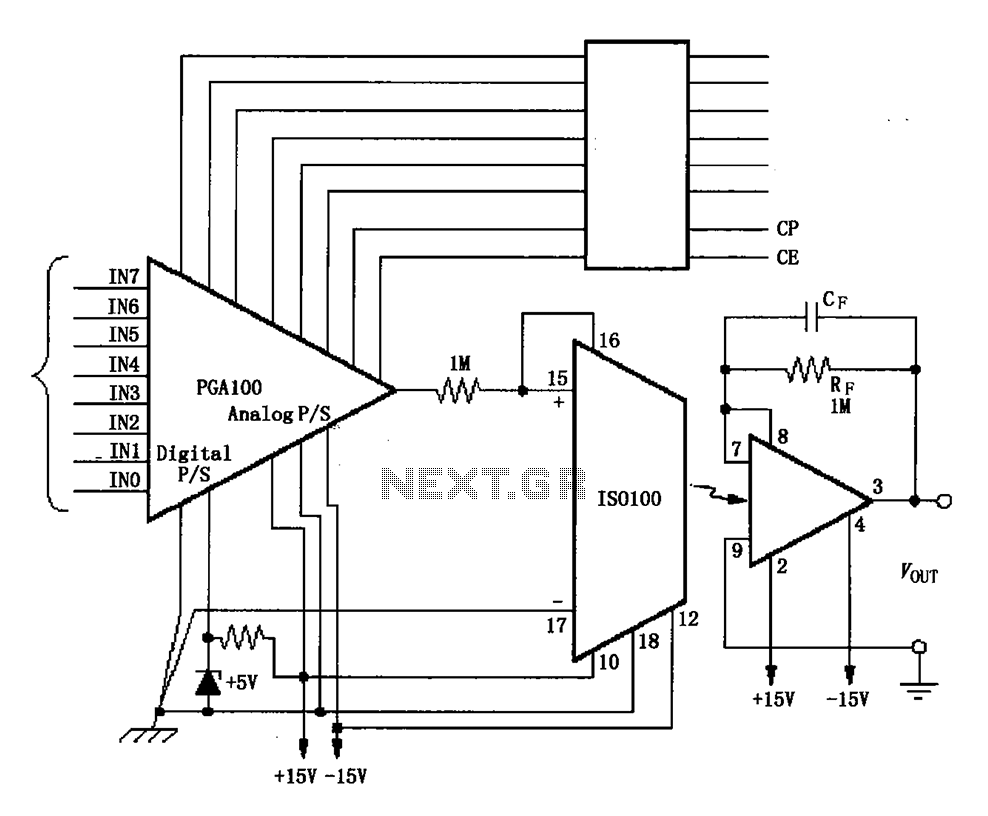
The ISO100 multichannel data acquisition system comprises a programmable gain amplifier isolated by an optocoupler, a programmable amplifier (PGA100), and an isolation amplifier (ISO100). The optocoupler selects three channels and is coupled to the programmable gain amplifier, which can...
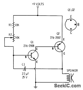
R2 controls the charging speed of capacitor C1. At a specific charge level, C1 triggers transistors Q1 and Q2, which release a 9-volt pulse. This pulse generates a clicking sound. The discharge process of the capacitor involves it charging...
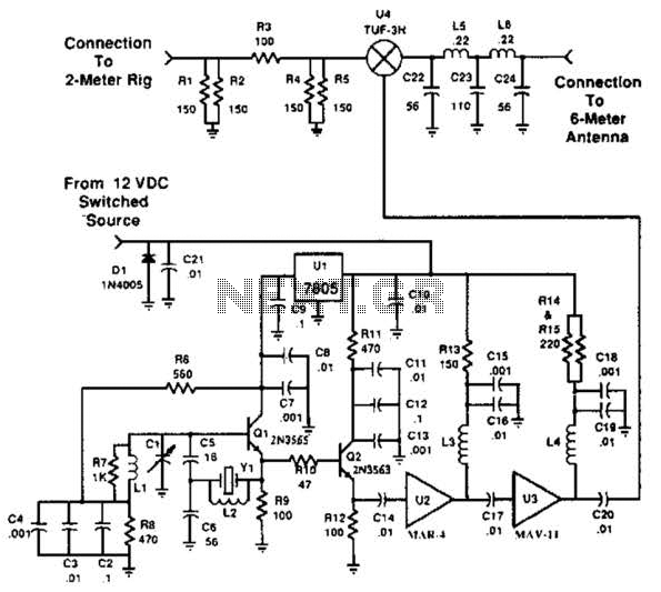
This transverter utilizes the bilateral properties of a balanced mixer to generate a 6-meter output from 2-meter inputs. The component Y1 is a 90-MHz crystal. It is important to note that the input frequency on the 2-meter band is...
In this circuit, the alarm is activated under four different conditions: 1. When light falls on LDR1 (located at the entry to the premises). 2. When light falling on LDR2 is obstructed. 3. When door switches are opened or...