
Automatic Headlight Brightness Switch Circuit
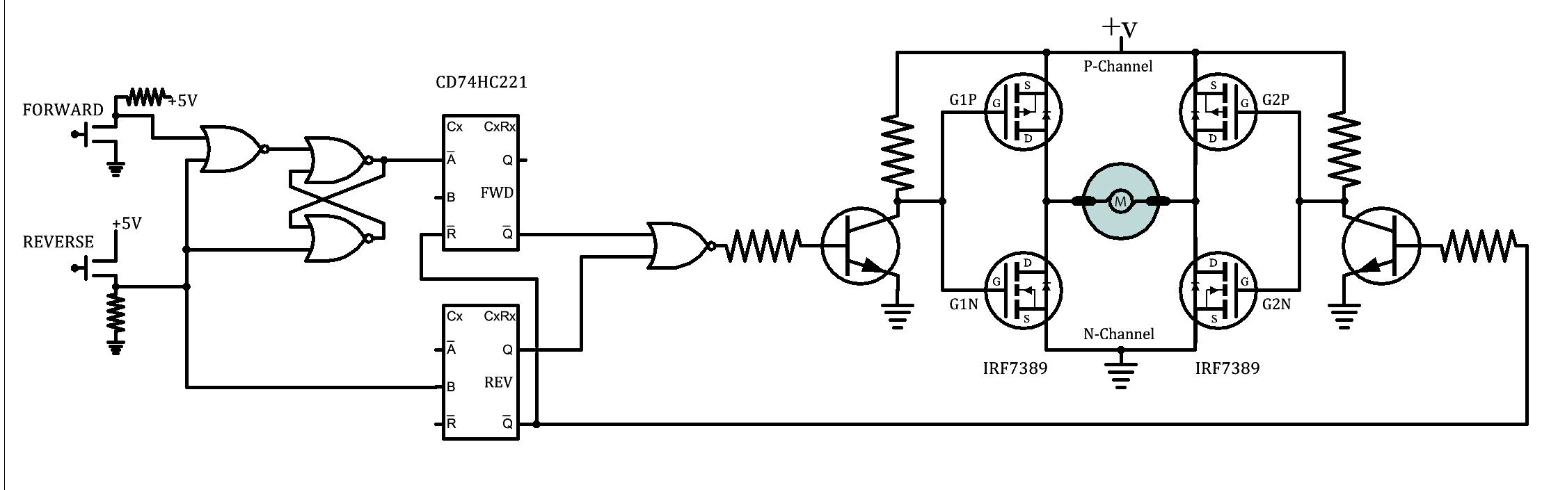
A circuit designed for automatic switching of high-beam headlights typically involves a light sensor, often a phototransistor or photodiode, that detects the intensity of incoming light. When the sensor detects the headlights of an oncoming vehicle, it triggers a transistor switch (Q1) that toggles the headlight circuit from high beam to low beam.
The circuit can be powered by the vehicle's electrical system, typically a 12V battery. The light sensor should be calibrated to ensure it only reacts to the specific wavelengths emitted by vehicle headlights, thus preventing false triggers from other light sources.
In terms of component selection, Q1 should be a robust N-channel MOSFET capable of handling the current required by the high-beam headlights. Additionally, resistors may be included to limit the current flowing through the sensor and to set the threshold for switching. A capacitor can be added to filter out noise from the sensor signal, ensuring stable operation.
The layout of the circuit should prioritize the placement of Q1 to maintain a direct line of sight with oncoming traffic, which can be achieved by mounting it in the dashboard or front grille. Proper installation and orientation of the sensor are crucial for the effective operation of the system, ensuring that it can reliably detect oncoming headlights and switch the beams accordingly.
This automatic headlight switching circuit enhances driving safety by allowing the use of high beams in low-traffic conditions while preventing glare for other drivers.Driving the artery with your high-beam headlights can absolutely access your visibility, but can he a blinding hazard for added drivers. This simple ambit can be active into your headlight about-face to accommodate automated switching amid aerial and low axle headlights back there is advancing traffic.
It does this by analysis the lights of that t raffic. In this way, you can drive cautiously with your high-beams on after blinding added drivers. 1. Q1 should me mounted in such a way so it points toward the front of the car with a clear line of site. Suitable places are on the dashboard, in the front grill, etc. 🔗 External reference
Related Circuits
A JFET-bipolar cascode circuit is designed to deliver complete video output for driving the cathode of a CRT. The configuration offers an approximate gain of 90. The cascode arrangement mitigates issues related to the Miller capacitance of the JFET...
A brief background is provided, indicating a basic understanding of electronics, including knowledge of component functions and schematic reading, but lacking further expertise. The circuit in question appears to involve fundamental electronic components, which may include resistors, capacitors, diodes, transistors,...
Solar panels operate at optimal parameters when positioned at the ideal angle to the sun. This alignment is achieved by rotating the solar panels to track the sun's movement. A DIY solar tracker system can be constructed using an...
Electronics tutorial on combinational logic circuits that utilize logic gates to create multiplexers, encoders, and solid-state switches. Combinational logic circuits are fundamental components in digital electronics, characterized by their ability to produce outputs based solely on the current inputs, without...
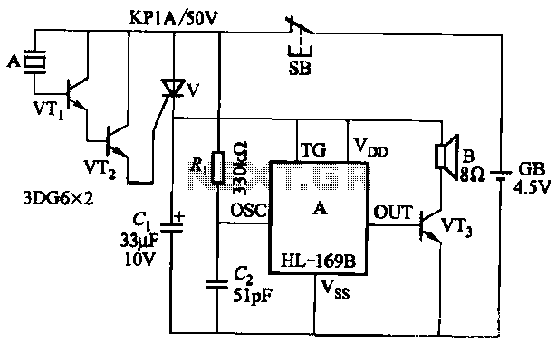
The circuit utilizes the HL-169B voice alarm integrated circuit (IC). It is designed for use in security applications, including glass doors, car doors, and windows, to act as a burglar alarm. When a thief applies force to these items,...
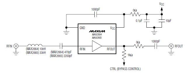
A simple, low-cost, and ultra-compact VHF/UHF low-noise amplifier circuit can be designed using the MAX2664 and MAX2665 ultra-compact LNAs for VHF/UHF applications. These devices incorporate a broadband LNA with an integrated bypass switch. The MAX2664 covers the UHF frequency...
Warning: include(partials/cookie-banner.php): Failed to open stream: Permission denied in /var/www/html/nextgr/view-circuit.php on line 713
Warning: include(): Failed opening 'partials/cookie-banner.php' for inclusion (include_path='.:/usr/share/php') in /var/www/html/nextgr/view-circuit.php on line 713