
7400 Siren

The circuit employs two NAND gates configured as an oscillator, which generates a square wave signal fundamental for producing audio tones. The oscillation frequency is primarily determined by the capacitors and the resistor in the timing network. In this configuration, the two NAND gates function as inverter stages, where the feedback loop formed by the resistors and capacitors dictates the oscillation frequency.
The use of 220 µF capacitors allows for a specific tone speed, which can be modified by substituting these capacitors with larger values. This adjustment results in a slower oscillation rate, effectively lowering the pitch of the generated tones. The capacitors of 0.2 µF and 0.1 µF are critical for fine-tuning the frequency; changing these components alters the charge and discharge times, thus affecting the output frequency of the oscillator.
R1 plays a vital role in the timing circuit; increasing its resistance will extend the oscillation period, thereby lowering the frequency. The 1.5 kΩ resistor is crucial for adjusting the frequency range between the two generated notes. By altering this resistor, the circuit can shift the pitch range, allowing for a broader spectrum of tones to be produced.
Overall, this oscillator circuit is a versatile design that can be easily modified by changing capacitor and resistor values, providing flexibility in sound synthesis applications.Two NAND gates are used for the oscillator, and two as the control. If the two-tone speed needs to be altered, the 220 µ capacitors can be changed Oarger for slower operation). If the frequency of the oscillator is to be changed, the 0.2 and 0.1 /iF capacitors can be varied and the value of Rl can be increased.
To change frequency range between the two notes, alter the 1.5 k (1,500) resistor= To change frequency range between the two notes, alter the 1.5 k (1,500) resistor.
Related Circuits

A two-transistor electronic siren breadboard circuit that produces an audible rising pitch on a loudspeaker. This circuit serves as a tutorial for beginners in electronics. The two-transistor siren circuit operates by utilizing the properties of transistors to create an oscillating...
An adaptable siren generator circuit with multiple applications is presented. It is based on a 556 twin-timer chip, IC1. One timer section generates an audio tone that is directly coupled to the driver transistor, TR1. The other half of...
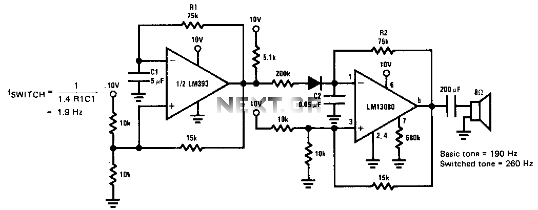
This siren provides a constant audio output while alternating between two distinct tones. The LM13080 is configured to oscillate at a fundamental frequency. This frequency can be modified by connecting a 200 kΩ charging resistor in parallel with the...
The sound produced imitates the rise and fall of an American police siren. When first switched on, the 10µF capacitor is discharged, and both transistors are off. When the push button switch is pressed, the 10µF capacitor will charge...
An individual is attempting to design an alarm using an LM555 timer but is unsure of where to begin. Friends who have experience in designing alarms are providing support. The LM555 timer is a versatile integrated circuit widely used in...
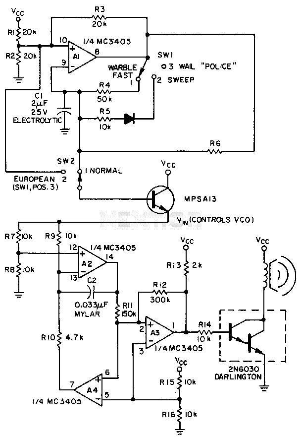
A low-frequency op-amp oscillator and a voltage-controlled oscillator (VCO), both configured using a single MC3405 dual op-amp and dual comparator, are the primary components in a siren circuit capable of producing various warbles and wails, or functioning as an...