
creating a two stage alarm siren
The LM555 timer is a versatile integrated circuit widely used in timer, delay, pulse generation, and oscillator applications. For designing an alarm system, the LM555 can be configured in either monostable or astable mode, depending on the desired functionality.
In monostable mode, the LM555 timer generates a single pulse when triggered. This configuration is suitable for applications where an alarm should sound for a specific duration upon activation. To set up the circuit, the following components are required: the LM555 timer IC, a resistor (R1), a capacitor (C1), a switch (to trigger the alarm), and a sound-producing element such as a buzzer or speaker.
The resistor and capacitor values will determine the duration of the alarm sound. The time period (T) for which the output remains high can be calculated using the formula T = 1.1 * R1 * C1. Selecting appropriate values for R1 and C1 will allow for customization of the alarm duration.
In astable mode, the LM555 operates as an oscillator, producing a continuous square wave output. This configuration can be used for alarms that need to sound intermittently. The circuit requires two resistors (R1 and R2) and a capacitor (C1) in addition to the LM555 timer. The frequency of oscillation and duty cycle can be adjusted by changing the resistor and capacitor values. The frequency (f) can be calculated as f = 1.44 / ((R1 + 2 * R2) * C1).
In both configurations, the output pin (pin 3) of the LM555 can be connected directly to a buzzer or speaker to produce sound. Additionally, a diode may be placed in parallel with the buzzer to protect the circuit from back EMF generated when the buzzer is turned off.
To enhance the design, a power supply circuit must be considered to ensure that the LM555 and the sound-producing element receive the required voltage levels. A 9V battery or a regulated power supply can be utilized. Proper decoupling capacitors should also be included to stabilize the power supply and prevent fluctuations.
In summary, designing an alarm using the LM555 timer involves selecting the appropriate configuration (monostable or astable), determining resistor and capacitor values for timing, and integrating a sound-producing element. With careful planning and component selection, a functional and customizable alarm system can be created.I am attempting to design an alarm using a LM555 timer. I dont know where to start. My friends around have been designing them and I am trying to make .. 🔗 External reference
Related Circuits

This is a siren sound generator circuit that is cost-effective and capable of producing simple sound patterns. The circuit utilizes IC1, which is a CD4011 (Digital NAND Gate), and IC2 is... The siren sound generator circuit is designed to produce...
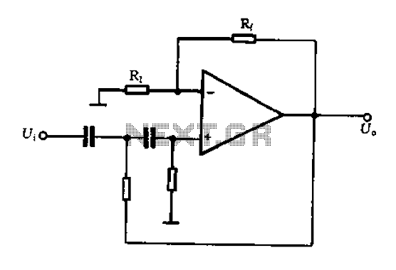
A typical two high-pass filter circuit. A high-pass filter (HPF) is an electronic circuit that allows signals with a frequency higher than a certain cutoff frequency to pass through while attenuating signals with frequencies lower than the cutoff frequency. A...
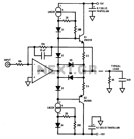
An output booster is required to achieve the necessary current or voltage gain. A significant output is often needed in conjunction with the output power limitations of most integrated circuit (IC) processors. The following figure presents a circuit diagram...
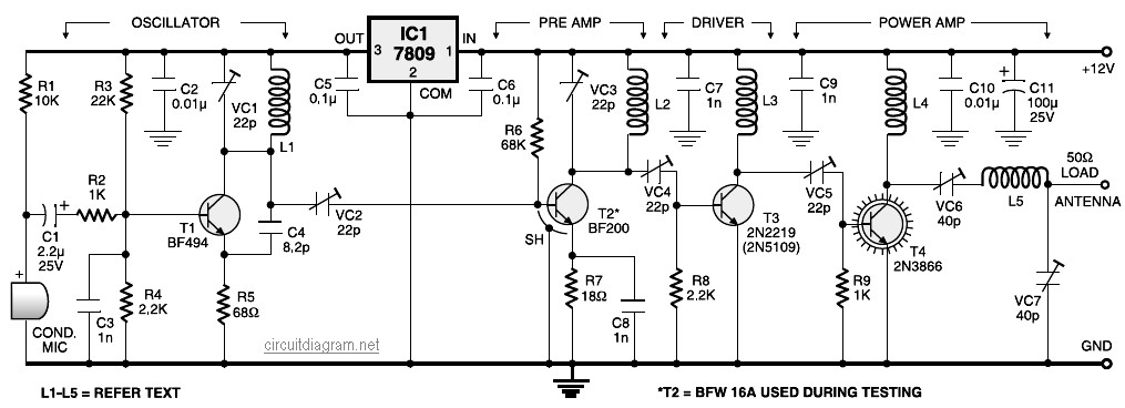
A four-stage FM transmitter circuit diagram utilizes four radio frequency stages: a VHF oscillator designed around the BF494 transistor (T1), a preamplifier based on the BF200 transistor (T2), a driver built with the 2N2219 transistor (T3), and a power...
Each zone uses a normally closed contact. These can be micro switches or standard alarm contacts (usually reed switches). Zone 1 is a timed zone which must be used as the entry and exit point of the building. Zones...
This system consists of two opto-isolated circuits that facilitate data transmission via an infrared network device between two computers. For instance, a user can transfer files from a desktop computer to a laptop computer without the use of cables,...