
8 Pin PIC Development Board
The prototype board is engineered to facilitate the development and testing of applications using 8-pin PIC microcontrollers. The integration of a 4 MHz ceramic resonator ensures stable clock frequency essential for microcontroller operation. The external 8K EEPROM (24C08 DIL8) supports I2C communication, allowing for data storage and retrieval, which is pivotal in applications requiring non-volatile memory.
The power supply section is designed to accept a broad range of input voltages, with the 78L05 voltage regulator providing a regulated output of 5 volts. This feature is crucial for ensuring that the microcontroller and other components receive a stable voltage, enhancing reliability during operation. The inclusion of filtering capacitors further stabilizes the power supply, reducing noise and voltage fluctuations that could affect performance.
The RS232 port, facilitated by a DB9 female connector, enables serial communication with other devices, making it suitable for debugging and data exchange. The RS232 interface circuit ensures compatibility with standard serial communication protocols, allowing for versatile application in various projects.
The design incorporates an extension slot for GPIO0-GPIO5, providing additional flexibility for connecting peripherals or sensors, while the grid spacing of 100 mils allows for easy integration with other prototyping boards or components. The board's dimensions and mounting holes facilitate convenient placement in various enclosures or test setups.
Overall, this prototype board combines essential features and components to create a robust platform for prototyping and experimenting with 8-pin PIC microcontrollers, making it an invaluable tool for engineers and hobbyists alike.Prototype board for 8 pin PIC microcontrollers with 4MHz ceramic resonator, external 8K EEPROM, power supply circuit, and RS232 port. Two small holes for for soldering in two DC power lines (Vdd/Gnd): anything above 7 volts will work, the 78L05 voltage regulator will take care of the rest.
This is a great test bed for many projects! Please note: There is no ICSP/ICD port. You can either wire your own ICSP port, or simply remove the chip for programming and reinsert it into the socket. FR-4, 1.5 mm (0.062"), green solder mask, white silkscreen component print Dimensions 43x81 mm (1.7x3.2") Voltage regulator 78L05 and filtering capacitors Stable 4MHz Ceramic Resonator I2C EEPROM - 24C08 DIL8 microcontroller socket RS232 DB9 female connector RS232 interface circuit Extension slot 6 pins for GPIO0-GPIO5 Grid 100 mils Four mounting holes 3.3 mm (0.13") 🔗 External reference
Related Circuits
Connect a PIC microcontroller to an RN-41 Bluetooth module. The PCB was not designed by the current user, so the rationale behind the circuit's design, which differs from the voltage divider method used by others, is unclear. The 5V...
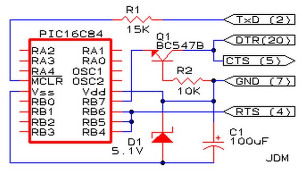
Affordable PIC Programmer. This programmer is compatible solely with the PIC16F84 microcontroller. It is reliable, as it rarely encounters errors, and functions well with nearly all computer systems, in contrast to some alternatives. The PIC programmer designed for the PIC16F84...
Five pins RA0 to RA4 are used as inputs. The pins are connected to the 5V average resistance 10K (Pull-up). So when no switch is not depressed all the pins have a high potential (HI +5 V). When one...
This device can be interfaced with various adapters, including a keypad adapter (optional), an RF receiver (optional), or via the internet (optional). It can also be adapted to operate with other external attachments. The device features multiple interfacing options, enhancing...
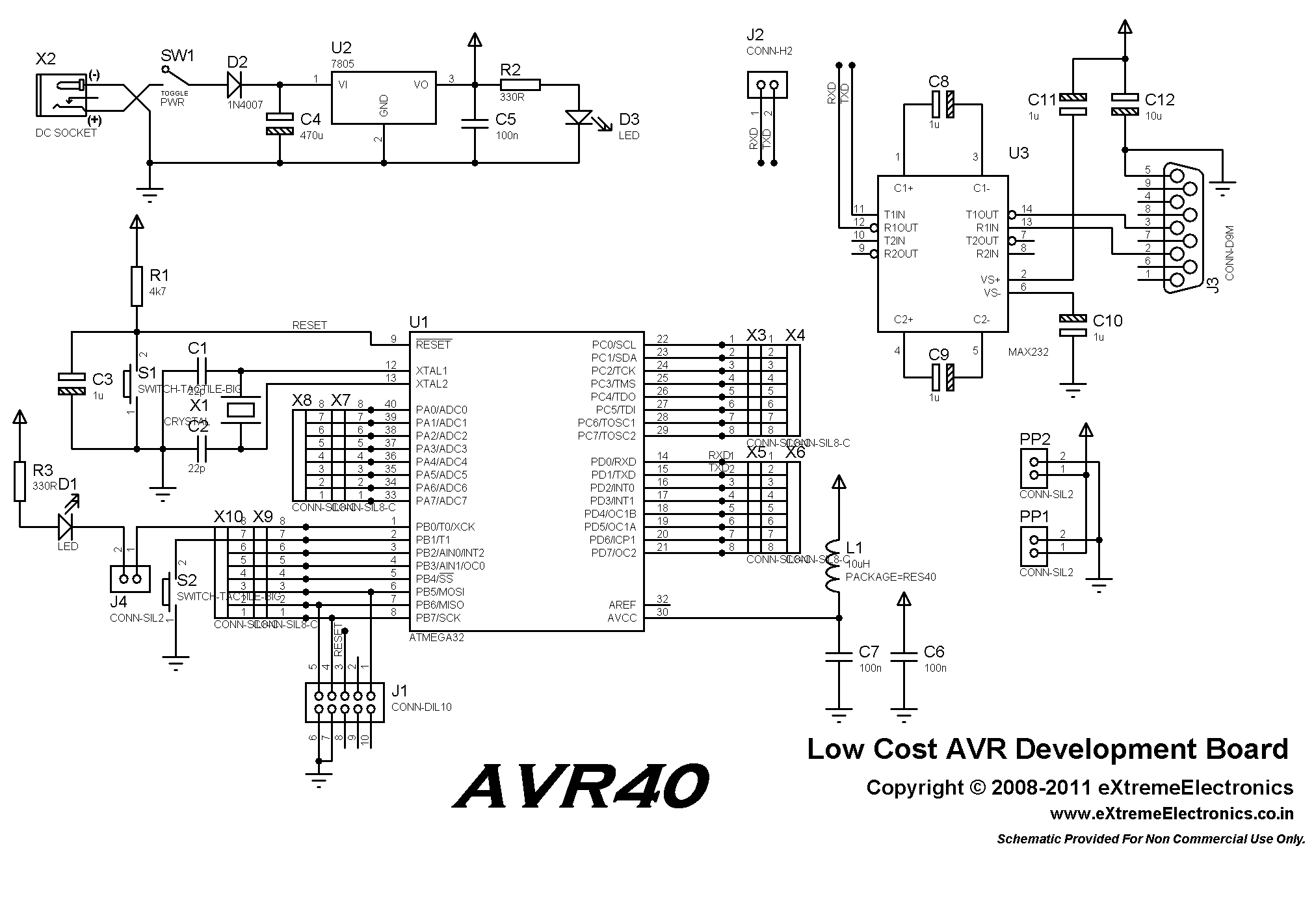
This low-cost AVR development board is designed for beginners to work with 40-pin AVR devices, facilitating easy testing and project development. When paired with a USB AVR Programmer, it serves as a comprehensive development and learning platform. The included...
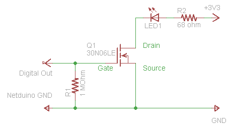
The process of driving an LED involves using a Power MOSFET to control the LED's state (On and Off) via a digital signal. This guide provides a step-by-step approach to wiring the circuit on a breadboard, which serves as...